

D300-03-00
Alarm
5
Test
Press OK x 2
Contaminated
Invalid
Attempting
Connection
LINK?...END
Device set
to Alarm
Connection
Failed
** Retry **
Chamber
FAULTY
Replace Unit
OK
OK
OK
Fail
Device
3.1
Address
Select Addr.
and press OK
01
Alarm
3.2
Sensitivity
LED
3.3
Operation
Set LED
Operation
--------
OK
Siren
3.4
Operation
Siren Sound
set to:
X
OK
Start
OK
INCREMENTAL
Address Mode
Write
3
Detector
Settings
OK
OK
OK
OK
OK
NEW Alarm
Sensitivity
--------
OK
OK
OK
OK
OK
OK
Attempting
Connection
LINK?...>END
Connection
failed
** Retry? **
OK
Fail
Success
OK
Esc
OK
OK
Fail
Success
Attempting
Connection
LINK?...>END
Connection
failed
** Retry? **
Select Addr.
and press OK
001
Device
Information
Missing
Start
OK
to Transmit
NEW Settings
Esc
Detector
Data
Corrupted
Esc
Low Battery
in RPTU
RPTU
Faulty!
Goodbye ...
Low Battery
in S300SAT
Will display “
Alarm Sensitivity
” for photo
and photo-thermal or “
Alarm Method
” for
thermal detectors.
Level will be “
Low
”, “
Medium
” or “
High
”
Method will be “
Fixed Temp
” or “
Rate of
Rise
”
Displays the date the detector was last serviced.
Displays whether the green LED on the detector is set to “
Blink
” or
“
No Blink
” in normal conditions.
Displays the date of manufacture
3: WRITE DETECTOR SETTINGS
Selects and writes new settings to the detector.
Use arrows to select the required
address (
01
to
99
) and press OK to
confirm.
Note: Only addresses 1 to 32 are
valid on the S300ZDU.
Use arrows to select alarm sensitivity
(
LOW
/
MEDIUM
/
HIGH
) and press
OK to confirm.
Note: Detectors are supplied set to
Medium sensitivity as default.
Use arrows to select siren sound -
from
1
up to
6
Note:
This function is not yet
available
Use arrows to select
No-Blink
- LED off on standby
Blink
- Green LED Blinking on standby
From the “
Start to Transmit NEW Settings
” Screen, press OK to send new settings
to the detector. The “
Attempting Connection
” Screen will be displayed for a few
seconds, and a bar graph will be displayed indicating progress. On successful
completion of programming, the RPTU will return to the “
Start Transmission
” screen.
If the “
Connection Failed
” screen appears, either communications have not been
established, or communications have been interrupted during transmission of the new
settings. Connection should be re-attempted by pressing OK.
Note: It is possible to return to the "
Start to Transmit NEW
Settings
" Screen directly from the "
Connection Failed
" screen by
pressing Esc once if communications were not been established, or
twice if the bargraph is displayed on the screen before communica-
tions were lost, and a sensitivity change was requested. However
extreme caution should be exercised: If communications with a detector had
started, then using the Esc button to return to the "
Start to Transmit NEW
settings
" screen can cause the detector's data to be lost, and the detector will
have to be returned to the supplier for reprogramming.
The “
Device information Missing
” screen appears to indicate that communication
has been attempted with an incompatible detector type for example an ECO1000. Press
“Esc” to return to the “
Start to Transmit NEW Settings
” Screen.
The “
Detector Data Corrupted
” screen will appear if an attempt is made to
reprogramme a detector which has previously been corrupted. Press “Esc” to return to
the “
Start to Transmit NEW Settings
” Screen.
Immediately following completion of the write sequence, the new settings should be
verified using “
Acquire Detector Settings
”, see section 2.
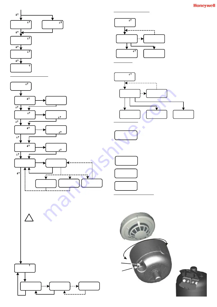
5: ALARM TEST
This will force the detector to run a chamber test and, provided the chamber is good, set the alarm
flag to put the detector into alarm. If the chamber is faulty or contaminated the relevant screen will be
displayed on the RPTU.
Note: Before running this test, notify the
proper authorities that the detector is
undergoing test.
Once the detector has been set into
alarm, communications with the
S300RPTU will be lost, and the detector
will need to be reset from the control
panel.
Press OK to return to the main menu
6: OTHER SCREENS
Other screens that may appear at any time include the following:
Batteries in the S300RPTU need replacing. With reference to the
diagram on the front page:
The battery is accessed by unscrewing the four screws (8) and
removing the rear cover.
Replacement batteries (7) are 3 x LR03.AAA Size 1.5V. Ensure that
correct polarity is used.
WARNING: Do not remove the back up button cell (6) at any time. This will cause RPTU
clock information to be lost, and the unit to stop working. Do not tamper with any part of
the circuit except the main batteries or permanent damage may be caused.
Batteries in the S300SAT Satellite unit need replacing. See S300SAT
instructions below for details.
Loss of information on the real time clock on the RPTU. This will disable
any further operation except to turn the unit off.
Note:
If this message appears, the S300 RPTU must be returned to
System Sensor for repair and reprogramming.
Displayed when the S300RPTU is switched off.
4: WRITE NEW SERVICE DATE
If the detector has been satisfactorily
serviced, this function will write the current
date to the detector as it’s new service date,
otherwise the S300RPTU will display a
warning that the detector is dirty or
contaminated. If the date has been
correctly programmed, the current date will
be displayed on the S300 RPTU screen.
Note: If Esc is pressed from the
“
Connection Failed Screen
”, it is
possible that an incorrect service date
would be recorded, however this will not
affect the functioning of the detector.
The Incremental Address mode will automatically program detectors
with sequential addresses. Use the arrows to select the initial address
in a sequence, and then press OK to program the detector. On
completion, the next address will automatically be selected, press OK to
program the next detector.
Important - See warning note above concerning use of Esc
button from the “
Connection Failed
” Screen.
7: S300SAT SATELLITE TEST UNIT
The S300SAT provides a radio link for communications between the S300RPTU tool and a series 300
detector over distances up to approximately 4.5m. It clips directly into position on the detector, with
the use of either a standard System Sensor or, via an adaptor, No Climb Products access poles.
To prevent cross communication where more than one unit is in use on a single site, the S300SAT and
S300RPTU may be set to an address for 00 to 15 - See RPTU setup for details.
Power On/Off
Switch
Power
Indicator
LED
To locate the S300SAT, locate the unit
over the detector, and rotate until it
drops into place. Apply gentle
pressure to press home. To remove
simply pull unit away from detector
Battery Compartment.
Takes 2 x MN1604
(6LR61) 9V alkaline
batteries (Not supplied)
Alarm
Sensitivity
-----------
Last
Service Date
DD MMM YYYY
Device's
LED Set to:
------------
Produced
in:
MMM YYYY
Alarm
Method
------------
Last
Service Date
DDMMYY
Attempting
Connection
LINK?...>END
Connection
Failed
** Retry? **
Contaminated
Invalid
OK
OK
Fail
Write
4
NEW
Service Date
!
I56-1720-003EN


