Honeywell RP920A Скачать руководство пользователя страница 5

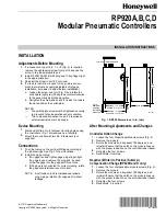
RP920A,B,C,D MODULAR PNEUMATIC CONTROLLERS 

2.   Install a 0 to 30 psi (0 to 207 kPa) gage in BLP test tap 

or in BLP gage port if one is not permanently installed. 

3.   Apply MLP to the system. 
4.   Adjust the authority knob to minimum. 
5.   Adjust the compensation startpoint knob until the 

receiver gage (port 5) reads the pressure equivalent of 
the compensation startpoint (W

c

) (Fig. 9 or 10). 

6.   If the compensation startpoint (W

c

) and desired 

startpoint do not match, remove the knob and replace it 
so they do match. 

7.   The compensation startpoint (W

c

) is now calibrated. 

NOTE:   The response of the receiver gage may be 

slow (up to one minute). The controller is not 
defective under these conditions. 

17.   Remove the CCT816B Calibration Unit and pipe

sensors. 

RP920C and D Systems 

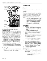
1.   Remove the integral module screw (Fig. 13) and install 

the 14003755-001 Barb Fitting and O-ring in its place. 

2.   Apply 8 psi (55 kPa) to the integral module. 
3.   Calibrate the RP920: 

a.   RP920C: follow the procedure for the RP920A. 
b.   RP920D: follow the procedure for the RP920B 

except that the calibration value of the BLP for 
Steps 10 and 15 should both be 8 psi (55 kPa). 

4.  When calibration is complete, remove the barb fitting 

from the integral module and replace the screw. 

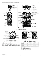
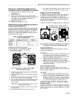
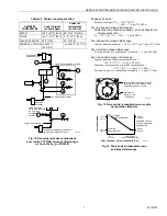
8.   Set up the CCT816B Calibration Unit (Fig. 11) to 

connect to port 3 (primary sensor). 

NOTE:   Sensors are not connected. 

FULL 
COMP 

SETPOINT 

(W 1) 

COMPENSATION 
STARTPOINT (Wc ) 

C5110 

COMPENSATION SENSOR 

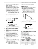
Fig. 9. Negative compensation calibration reset schedule. 

C5109 

PRIMARY SENSOR

THE GAGE RANGE MUST 

8

5

MATCH THE RANGE OF THE 
SENSOR FEEDING PORT 5 

3

PRIMARY 
SENSOR 

Fig. 8. Piping for RP920B compensation 

startpoint (W

c

) setting. 

9.   Apply a pressure equivalent of the primary sensor value 

corresponding to the compensation start (comp start) on 
the reset schedule (Fig. 9 or 10). 

10.   Adjust the setpoint knob until the BLP equals the 

expected pressure of the controlled device at comp start 
conditions. 

11.   If needed, remove the setpoint knob and replace it 

so the setpoint matches the primary sensor value at
comp start

12.   The setpoint (W

1

) is now calibrated. 

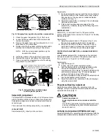
13.   Set up the CCT816B Calibration Unit (Fig. 12) to

connect to port 3 (primary sensor) and port 5
(compensation sensor). 

14.   Apply sensor input pressures equivalent to the full 

compensation on the building schedule. 

15.   Adjust the authority (A

c

) knob until the BLP equals the

expected pressure of the controlled device at full
compensation conditions. 

16.   Calibration is complete. 

IMPORTANT 

PRIMARY SENSOR

FULL 
COMP 

SETPOINT 

(W1 ) 

COMPENSATION 
STARTPOINT (Wc ) 

COMPENSATION SENSOR 

C5111 

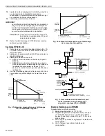
Fig. 10. Positive compensation calibration reset schedule. 

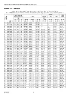
RP920B Calibration Example 

Assume the following conditions: 
— A 10°F (5.6K) throttling range. 
— Using a 2.5 to 6.5 psi (17 to 45 kPa) operator with a 

normally open (N.O.) valve where conditions are: 6.5 psi 
(45 kPa) with no load and 2.5 psi (17 kPa) with full load. 

— See Fig. 14 for the schedule graph. 
— See Table 2 for the reset schedule. 

Table 2. Reset Schedule. 

Changing compensation startpoint (W

c

) or setpoint 

(W

1

) affects only the one corresponding value of the 

reset schedule, while changing authority (A

c

) affects 

only the slope of the reset schedule. 

NOTE:   See the Compensation Startpoint (W

c

Adjustment section for more information. 

Compensation 

Range 

Primary Sensor 

(Discharge) 

Compensation 

Sensor (OA) 

Start 

120°F (49°C) (40%) 

60°F (16°C) (50%) 

Full 

160°F (71°C) (60%) 

0°F (-18°C) (20%) 

Operating Span  40°F (22K) 

60°F (33K) 

Sensor Range 

40 to 240°F 
(4 to 116°C) 

-40 to 160°F 
(-40 to 71°C) 

5  

95-7392EF 

Содержание RP920A

Страница 1: ...he job drawings See Fig 2 for port locations 2 Install the gage or plug a If no gage is used tighten gage plugs finger tight If a gage is used remove the plug and by hand screw the gage into the gage port three turns b If the gage is not oriented for correct viewing rotate the gage counterclockwise until correct NOTE A soft rubber factory installed seal allows plug or gage rotation for alignment w...

Страница 2: ...NT 8 CLOSED REMOTE SETPOINT 9 CPA 4 8 9 1 3 2 7 6 5 1 RP920B D ONLY RP920C D ONLY 2 Fig 2 Module and port Locations C5102 2 3 1 Connector Block Module SENSOR SUPPLY OPEN SENSOR SUPPLY BLOCKED EXTERNAL RESTRICTOR SCREW SWITCHPLATE POSITION INDICATOR BLOCKED POSITION SWITCHPLATE OPEN POSITION 20 4 5 5 10 3 0 4 0 X p DIR REV DIR REV 20 4 5 5 10 3 0 4 0 X p NOTE LOCATION OF NOTCH DIRECT ACTING REVERSE...

Страница 3: ...late overlay notch Fig 7 2 Adjust the setpoint W1 according to the job drawings using the setpoint knob 3 If the control point deviates excessively from the setpoint W1 calibrate taking the throttling range into consideration REMOTE SETPOINT Setpoint W1 is controlled from 0 to 100 percent of the primary sensor span from a remote 3 to 15 psi 21 to 103 kPa bleed type signal Adjustments 1 Adjust the ...

Страница 4: ...field calculated values listed on the job drawing This controller startup approach will be adequate for most systems If it is determined that closer calibration is required use the following procedures NOTES The controller allows all adjustments to be made independently For example changing the proportional band Xp setting does not affect the calibration of the setpoint W1 compensation startpoint ...

Страница 5: ...n startpoint Wc setting 9 Apply a pressure equivalent of the primary sensor value corresponding to the compensation start comp start on the reset schedule Fig 9 or 10 10 Adjust the setpoint knob until the BLP equals the expected pressure of the controlled device at comp start conditions 11 If needed remove the setpoint knob and replace it so the setpoint matches the primary sensor value at comp st...

Страница 6: ...SI 55 kPa For Calibration Step 10 Desired BLP 6 5 psi 45 kPa INTEGRAL For Calibration Step 15 MODULE Primary sensor at full compensation C5114 160 F 71 C 10 2 psi 70 kPa Compensation sensor at full compensation Fig 13 Integral module piping 0 F 18 C 5 4 psi 37 2 kPa Expected BLP 2 5 psi 17 kPa 160F 71C 120F 48C PRIMARY SENSOR FULL COMP SETPOINT W 6 5 PSI 45 5 kPa 2 5 PSI 17 5 kPa EXPECTED BLP 1 0F...

Страница 7: ...de la canalisation principale d alimentation en air Installation de l appareil 1 À l aide du régulateur comme gabarit ou après avoir consulté l encombrement à la Fig 1 marquer et percer deux ouvertures de montage pouvant recevoir des attaches no 8 2 Installer le régulateur au moyen de deux attaches no 8 non fournies 75 3 DÉGAGEMENT MINIMAL 102 4 86 3 3 8 7 9 32 RP920A 36 1 1 2 RP920B D 83 3 1 4 14...

Страница 8: ...1 0 0 W1 DIR REV RP920A Bloc de raccordement Module du point de consigne Module de régulation proportionnelle 2 3 1 PRISE D ESSAI PRESSION SECONDAIRE ORIFICE DU MANOMÈTRE DU CAPTEUR PRIMAIRE PRISE DE MANOMÈTRE RP920A 1 2 PRISES DE 4 8 9 1 3 2 7 6 5 2 RP920B D SEULEMENT Fig 2 Emplacement des modules et des orifices Bloc de connexion ALIMENTATION DU CAPTEUR OUVERTE PLAQUE DE COMMUTATION INDICATEUR D...

Страница 9: ...s 7 Raccorder les composants de commutation du blocage de l action intégrale aux orifices 6 et 7 selon le cas Réglage du point de consigne W1 Le bouton de réglage du point de consigne W1 est marqué en relief d une échelle allant de 0 à 100 cette échelle correspond aux valeurs énumérées au Tableau 3 voir Annexe Plusieurs caches accompagnent le régulateur pour que le bouton de réglage puisse corresp...

Страница 10: ...itué sur le module de compensation Fig 2 Réglage du point de départ de la compensation Wc RP920B et D seulement Régler le point de départ de la compensation Wc selon les plans tableau de compensation à l aide du bouton de réglage du point de départ de la compensation Wc Fig 2 Dans le cas de capteurs à action directe le réglage du bouton est égal à la valeur de compensation correspondant à la valeu...

Страница 11: ...pteur de compensation ou un manomètre de 0 à 30 psi 0 à 207 kPa dans l orifice 5 comme l illustre la Fig 8 REMARQUE Si le régulateur comporte un manomètre de compensation dans l orifice de manomètre adéquat bloquer l orifice 5 et utiliser le manomètre existant 2 Installer un manomètre de 0 à 30 psi 0 à 207 kPa dans la prise d essai de la canalisation secondaire ou dans l orifice de manomètre de la...

Страница 12: ... étapes 10 et 15 devraient toutefois être de 8 psi dans 55 kPa dans les deux cas 4 Une fois l étalonnage terminé retirer le raccord à crans du module de régulation intégrale et remettre la vis en place CAPTEUR PRIMAIRE POINT DE CONSIGNE W1 CAPTEUR DE COMPENSATION PLEINE COMPENSATION POINT DE DÉPART DE LA COMPENSATION Wc DÉPART COMPENSATION CF5110 Fig 9 Tableau de compensation pour l étalonnage de ...

Страница 13: ...départ point de départ de la compensation Wc W 60 F 15 C 50 9 psi 62 kPa c Pour la neuvième étape d étalonnage Capteur primaire au départ 120 F 49 C ou 7 8 psi 53 8 kPa Pour la dixième étape d étalonnage Pression désirée à la canalisation secondaire 6 5 psi 45 kPa Pour la quinzième étape d étalonnage Capteur primaire à la pleine compensation 160 F 71 C 10 2 psi 70 kPa Capteur de compensation à la ...

Страница 14: ...8 33 1 70 9 26 5 26 3 10 23 70 21 5 21 27 3 39 4 43 6 57 5 14 16 4 9 33 9 71 3 27 3 27 8 22 72 22 4 20 29 1 40 4 44 7 58 14 17 5 0 34 7 71 7 28 1 27 8 6 21 74 23 3 19 31 0 41 5 45 7 58 5 15 18 5 2 35 6 72 1 28 8 28 5 4 20 76 24 2 19 34 1 42 6 46 8 59 15 19 5 3 36 4 72 5 29 6 29 3 2 19 78 26 1 18 36 2 43 6 47 8 59 5 15 20 5 4 37 2 72 9 30 4 30 0 18 80 27 0 18 38 3 44 7 47 5 9 60 16 21 5 5 38 1 73 8...

Страница 15: ...4 1 55 5 52 5 70 21 150 66 35 2 112 44 81 27 79 26 77 5 25 56 9 7 67 0 84 4 56 1 53 72 22 152 67 36 2 114 46 82 28 80 27 78 26 57 9 8 67 8 84 6 56 8 53 5 74 23 154 68 37 3 116 47 83 28 81 27 78 8 26 58 10 0 68 7 84 8 57 5 54 76 24 156 69 38 3 118 48 84 29 82 28 79 26 59 10 1 69 5 85 1 58 1 54 5 78 26 158 70 39 4 120 49 85 29 83 28 79 5 26 60 10 2 70 0 85 3 58 8 55 80 27 160 71 40 4 122 50 86 30 84...

Страница 16: ...3 3 80 4 71 5 146 63 226 108 73 23 182 83 119 48 115 46 96 5 36 94 14 3 98 5 93 5 81 1 72 148 64 228 109 74 23 183 84 120 49 116 47 97 36 95 14 4 99 3 93 8 81 7 72 5 150 66 230 110 75 24 185 85 121 49 117 47 97 5 36 96 14 5 100 1 94 82 4 73 152 67 232 111 76 24 187 86 122 50 118 48 98 37 97 14 6 100 9 94 3 83 73 5 154 68 234 112 77 25 188 87 123 51 119 48 98 5 37 98 14 8 101 8 94 5 83 7 74 156 69 ...

Отзывы: