background image

Document 800-02607V3 Rev A

47

11/09

4

Audio

This chapter covers:

Checking for audio interference

Monitoring and recording audio remotely and onsite using LocalView

Note

For Rapid Eye V8.1 DVRs offering HVA, LocalView cannot be used to monitor 
audio. Only network settings are available. To monitor audio using these 
DVRs, use the Rapid Eye Remote View application.

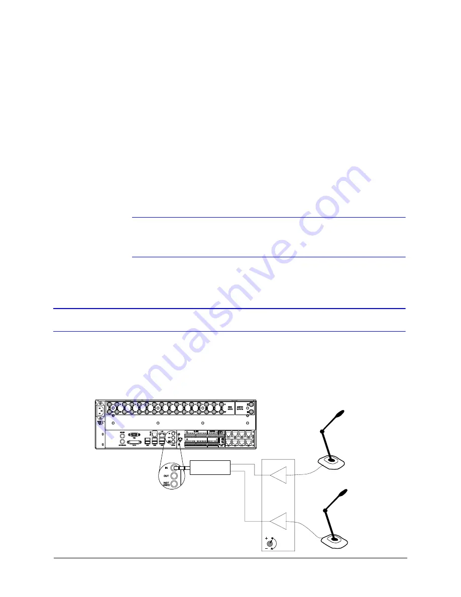
Audio at a Multi-Media Site

If security procedures call for viewing the person that is speaking, plan to place 
microphones in camera range. However, microphones can be placed independently of 
cameras; they have their own cabling. Microphones require amplification to provide 
line-level input to a Multi-Media DVR (see 

Figure 4-1

).

Figure 4-1

Audio Input to Multi-Media DVR

Channel 1 LEFT
Microphone

Channel 2 RIGHT
Microphone

MIC
INs

Line-level
OUTs

Mono
INs

Stereo mini- 
plug OUT

Mono-to-stereo 
adapter

GAIN

Pre-amplifier

Note

NOT USED is 
disabled; use 
AUDIO IN.

Содержание Rapid Eye

Страница 1: ...Document 800 02607V3 Rev A 11 09 Installation Guide Rapid Eye Multi Media Digital Video Recorder ...

Страница 2: ......

Страница 3: ...Installation Guide ...

Страница 4: ...e RE3 Phase 2 software release Features such as simplex audio the virtual keyboard archival policies and logs have all been added or updated V3 Rev A 11 09 Document updated for the latest Rapid Eye V9 0 software release 12 09 New features include full LocalView on Active Alert units the ability to disable LocalView and the option to set the bandwidth throughput as High Low All drawings of the back...

Страница 5: ...ling the Rapid Eye unit its components and configuring your network settings Chapter 3 Quick Test for Remote Video describes a quick test to confirm that all the Rapid Eye hardware and software is working properly Chapter 4 Audio identifies procedures to check for audio interference and to monitor and record audio data Chapter 5 Site Hardware shows how to add hardware to a Multi Media DVR and then...

Страница 6: ...nstallation If this equipment does cause harmful interference to radio or television reception which can be determined by turning the equipment off and on the user is encouraged to try to correct the interference For example try reorienting or relocating the receiving antenna increasing the separation between the equipment and receiver or connecting the equipment to an outlet on a different circui...

Страница 7: ...ons company The equipment must also be installed using an acceptable method of connection The customer should be aware that compliance with the above conditions may not prevent degradation of service in some situations Repairs to certified equipment should be coordinated by a representative designated by the supplier Repair or alteration made by the user to this equipment or equipment malfunctions...

Страница 8: ...ble 2 1 on page 23 Other connectors BNC video IN OUT public display PC mouse PC keyboard RJ 11 dial up RJ 45 LAN USB audio card OUT MIC IN screw terminal connectors ALARM CONTROL and custom RJ 45 serial ports Network access Auto sensing for 100BaseT or 10BaseT LAN WAN use through DSL or cable Modem Internal Programmable Complies with FCC ACTA Part 68 Industry Canada TBR 21 Public Switched Telephon...

Страница 9: ...ormation please refer to the documents listed in the table below included on the Documentation CD that came with your Rapid Eye unit Find the latest versions of these documents on the Honeywell Video website see www honeywellvideo com products recorders Document title Description Rapid Eye Multi Media Digital Video Recorder System Administrator Guide This guide is written for system administrators...

Страница 10: ...s displayed on the screen Syntax The message Unauthorized displays object entered Swiss721 BT Bold Words or characters that you must type The word enter is used if you must type text and then press the Enter or Return key Enter the password Menu titles and other items you select Double click Open from the File menu Buttons you click to perform actions Click Exit to close the program Italic Placeho...

Страница 11: ... Remotely 21 Storage Estimator 22 Background Information 22 2 Installation 23 Before You Begin 23 Unpack Everything 23 Overview of the Installation Procedure 24 Recording the Installation Details 25 Rear Panel Connections 25 Connecting a Camera 26 Rapid Dome or Rapid Dome Gold Dome Systems 27 Detachable Camera I O 27 Securing a Camera 28 Powering the Multi Media DVR 28 Powering Up 29 Powering Down...

Страница 12: ...r Detection for Cameras 44 Calibrating Rows of Mobile Objects 45 Firewall Reference 45 4 Audio 47 Audio at a Multi Media Site 47 Checking For Audio Interference 48 Audio for Operators 49 Sending and Receiving Audio Offsite 49 Monitoring and Recording Audio 50 Enabling Talking to a Site 50 Onsite Audio Using LocalView 50 Disabling Audio for LocalView 50 5 Site Hardware 51 Securing a Multi Media DVR...

Страница 13: ...l Modem 64 Appendix A Frequently Asked Questions 65 Supporting an Installation 65 Appendix B Cabling 67 Coaxial Cable 67 Triaxial Cable 68 Grounding 68 Electrical Interference 68 Appendix C Site Information Checklists 69 Organization 69 Site Definition 69 Communications to DVR 70 Communications from DVR to Alarm Station 71 Audio 71 Video Camera Configuration 72 Sensor Hardware 73 Control Outputs 7...

Страница 14: ...14 Contents ...

Страница 15: ...tings 37 Figure 2 12 TELCO Port Used for Dial up Connection 37 Figure 3 1 Desktop Icon for the Admin Application 41 Figure 3 2 Running a Maintenance Session 42 Figure 3 3 Select a Site on the Sites Tab then Click Live 43 Figure 3 4 DVR Base IP Ports Remote Connection and Alarm Station 46 Figure 4 1 Audio Input to Multi Media DVR 47 Figure 4 2 Connecting Speakers 48 Figure 4 3 Audio Tab 49 Figure 5...

Страница 16: ...16 Figures ...

Страница 17: ...lt Settings of the Internal DVR Modem 38 Table 2 4 Media Options for Video Clips 40 Table 3 1 Default Transmission Control Protocol TCP Ports 45 Table 5 1 Wiring an RJ45 Cable for Serial Use 52 Table 5 2 PTZ Drivers for Controllers and Domes 56 Table 5 3 Sensor Hardware 58 Table A 1 Installation FAQs 65 Table B 1 Recommended Maximum Length of Coaxial Cable 67 Table B 2 Coaxial Cable Checklist 67 ...

Страница 18: ...18 Tables ...

Страница 19: ...onal computer PC Connect a VGA monitor and mouse directly to the DVR to use LocalView onsite With a PC for remote access using View and Admin software For more information see Chapter 2 Installation Note Installers need to use LocalView briefly to change the IP Address of the DVR Availability of LocalView on V9 DVRs Offering Video Analytics LocalView is now fully supported by Rapid Eye s latest V9...

Страница 20: ...ote View Operator Guide for more information Connecting Cameras Connect a coaxial cable of each camera maximum 16 to the Multi Media DVR Connect the first camera to Video Input In 1 the second to Video Input 2 and so on For more information see Connecting a Camera page 26 and Cabling on page 67 Communications Connect the Multi Media DVR to a network to a telephone line or both See Figure 1 1 Figur...

Страница 21: ...ly using View software via a network connection you need to set up LocalView Note For remote operations using only dial up you do not need to set up LocalView Next Steps The following chapters in this guide provide detailed procedures and reference materials starting with Chapter 2 Installation Operating the DVR Remotely If you plan to perform a quick connection after the installation to connect r...

Страница 22: ...d then 1 Select the Start menu All Programs Rapid Eye Multi Media 9 0 2 Click Storage Estimator 3 Click OK on the About Storage Estimator window that appears 4 Change the recording options in the Estimator as needed and click Apply Options to obtain an estimate of your system s storage capacity See the Rapid Eye Multi Media Digital Video Recorder System Administrator Guide for more information on ...

Страница 23: ...ck Everything Check that the items received match those listed on the order form and packing slip The items you receive will depend on your unique system requirements Your kit can include Table 2 1 Contents of Rapid Eye Hardware Kit 100 01205 Itema Part Power Cord P8137 Rack ears brackets and screws for optional DVR mounting SARE2EARS Network CAT5 cable RJ45 connections 2 m length K9530 Modem cabl...

Страница 24: ...pplier will ask for the DVR serial number and will assign a Return Merchandise Authorization RMA number 3 Make a note of the RMA 4 Repack the DVR in its box along with the other contents 5 Prominently display the RMA on the shipping carton 6 Return the packaged DVR to the location specified by your supplier Overview of the Installation Procedure After unpacking the DVR 1 Connect one or more camera...

Страница 25: ...0 Recording the Installation Details As you start connecting hardware to the Multi Media DVR Honeywell recommends that you make a record of system information such as IP address with the site information checklist provided in Appendix C Include a record of the hardware connected to the DVR and changes to the Rapid Eye site configuration using LocalView Rear Panel Connections Figure 2 1 shows the r...

Страница 26: ... port on the DVR for the USB mouse supplied KEYBOARD For a standard keyboard not supplied TELCO RJ11 connector to the modem of the Multi Media DVR USB PORTS Can be used for USB devices such as the supplied USB mouse LAN RJ45 connector to 10 100 BT network card in the DVR AUDIO IN OUT Sound card connectors NOT USED DISABLED use AUDIO IN ALARM INPUTS Screw terminal connectors for input and ground co...

Страница 27: ...sitive to bad connectors do not use screw type connectors These can seriously compromise the performance of your DVR Rapid Dome or Rapid Dome Gold Dome Systems With Rapid Dome or Rapid Dome Gold dome systems using twisted pair transmission Honeywell recommends that passive to passive transmission distances be no more than 500 feet 154 meters For greater distance please use an active receiver such ...

Страница 28: ...allation Problems for Video on page 43 Powering the Multi Media DVR Multi Media DVRs can auto range 100 240 V 50 60 Hz Caution This equipment shall be connected to a grounded earthed outlet Do NOT remove or defeat the ground pin of the 3 prong electrical plug For many cameras in a permanent installation you can use a power supply such as an HPTV2404UL 4 cameras or HPTV2416UL 16 cameras A Multi Med...

Страница 29: ...tinue to record video during a power outage whether the outage is due to your utility or to a security violation Figure 2 4 Plugging in a Multi Media DVR Powering Up During the two minutes that the DVR needs to initialize it is good practice to not turn it off see Unit Recovery page 30 The end of the initialization is signaled by a double beep from the DVR 1 Plug the Multi Media DVR and its camera...

Страница 30: ...ke many hours even dozens of hours on DVRs with a large storage capacity If unit recovery occurs repeatedly contact Honeywell Technical Support see the back cover of this manual for contact information Rapid Eye Unit Installation Environment Installation of the equipment in a partially or completely enclosed space such as a multi unit rack or lock box should be such that the amount of air flow req...

Страница 31: ... exhaust vents in the enclosure should align with the intake and exhaust vents on the Rapid Eye unit to maintain proper air flow see Figure 2 6 During operation the maximum ambient temperature measured directly at the air intake vent of the Rapid Eye unit must never exceed the maximum operating temperature of 104 F 40 C Figure 2 6 Rapid Eye Unit Air Circulation Caution Units that are operating in ...

Страница 32: ...com support downloads downloads_dvr html to download the latest Rapid Eye software Availability of LocalView on V8 1 DVRs Offering Video Analytics On Rapid Eye V8 1 units offering Honeywell Video Analytics HVA LocalView can only be used to change the unit s network settings as in Using LocalView to Modify the IP Address of the DVR on page 33 Use the Admin and View applications to monitor video and...

Страница 33: ... at the front or rear of the Multi Media unit 2 The USB ports on the front and rear of the DVR can also be used to connect a USB flash drive commonly called a memory stick and or a USB keyboard not included The USB flash drive can be used for storing video clips Using LocalView to Modify the IP Address of the DVR If a remote network connection is needed configure the IP Address of the DVR using Lo...

Страница 34: ...the next few pages the Quick Setup Wizard and Help are not needed Remote Connection After an IP address has been assigned to the DVR a remote connection can be setup using the Admin application Refer to the Rapid Eye Multi Media Digital Video Recorder System Administrator Guide Note For dial up connections LocalView is not needed to help set up a remote connection Using the Virtual Keyboard Use th...

Страница 35: ... DHCP 1 In Network Settings enable DHCP on the Rapid Eye DVR see Figure 2 10 By default the Site Name in LocalView shows REM hyphen DVR serial number and includes the leading zeroes The DVR serial number is also printed on a sticker affixed to the DVR If you change the Site Name make a note of the new name for setting up a remote connection using the Admin software 2 Click Refresh 164 178 32 1 If ...

Страница 36: ... 2 Note DHCP can change an address if it is not reserved compromising future attempts to connect to the DVR Network Address Translation Using an Internet Router Match the DVR Gateway to the Internet Router Inside IP 1 In Network Settings use the virtual keyboard to enter the DVR IP Address as given out by the Network Administrator of the remote LAN 2 In the Gateway field use the virtual keyboard t...

Страница 37: ...a Network Connection in the Field To test a network connection PING the DVR Dial up Connection Figure 2 12 TELCO Port Used for Dial up Connection 1 Using a standard telephone cable with RJ11 connectors plug one connector into the TELCO port on the DVR see Figure 2 12 2 Plug the other connector in a telephone outlet 164 178 32 1 Telco port ...

Страница 38: ...ine used by a Multi Media DVR Note For dial up connections LocalView is not needed to help set up a remote connection You are ready to power up the camera s and the DVR See Powering the Multi Media DVR on page 28 DVR Internal Modem Default Settings Testing a Dial Up Connection in the Field Using a standard telephone line dial the number used to reach the DVR modem to listen for an answer tone Tabl...

Страница 39: ...front cover of the Multi Media DVR If the cover is locked use the key supplied with the DVR 2 Open the DVD drive 3 Place the CD identified as UPGRADE into the tray 4 Shut the DVD tray 5 While the CD ROM remains in the DVR power down the DVR 6 Power up the DVR 7 Check the blue LCD As the DVR starts up a set of messages appear Honeywell Startup Shell Do Not Restart Upgrading Unit Upgrade Complete Re...

Страница 40: ...o feeds or by shortening the clip Making and Copying a Clip from a PC Running View Operators who make video clips offsite using a PC running the View application can copy one clip or many using the hardware on the PC LocalView Features on V9 DVRs Offering Video Analytics LocalView is now fully supported by Rapid Eye s latest V9 software and can be used to make clips see Availability of LocalView o...

Страница 41: ...s and so on Software for the Remote Operation of Rapid Eye DVRs Checklist for Admin Software Figure 3 1 Desktop Icon for the Admin Application Refer to the Rapid Eye Multi Media Digital Video Recorder System Administrator Guide about using Admin software to Open the ports in your organization s firewall that are needed by Rapid Eye See Firewall Reference page 45 Install Rapid Eye Multi Media REM s...

Страница 42: ... Multi db Name the Rapid Eye site Add connection information about the Rapid Eye site Checklist for View Software Refer to the Rapid Eye Multi Media Digital Video Recorder System Administrator Guide about using the View application to 1 Run View 2 Log on to the Multi db 3 Using View run a Maintenance session at the Rapid Eye site to check if the connection is set up After one Maintenance Session r...

Страница 43: ...or Guide about using View to run a Live session and obtain video Figure 3 3 Select a Site on the Sites Tab then Click Live Avoiding Installation Problems for Video After a successful quick connection check the recorded video for hard to predict situations Changing environmental factors can compromise video at the source Tear away Player window Player toolbar Image from video feed ...

Страница 44: ...prevent easy criminal tampering with the system Dew frost or kitchen grease Check camera lenses or windows between the camera and the subject for transparency and cleanliness Darkness Without lighting or infrared cameras indoor rooms and nighttime can make cameras ineffective Cameras at an outside window In a room that remains lit during evenings reflection from the window can hamper or block visi...

Страница 45: ...ions will trigger Blur and Scene Change Calibrating Rows of Mobile Objects Scene Change is sensitive to large scale changes in a scene For example using Scene Change for a camera that shows many chairs in a row close by such as in an airport or casino may not be effective If the DVR learns while people are sitting that sitting persons are not to be considered as sabotage when the chairs empty the ...

Страница 46: ...tation 10 003 Alarm Alarm server for callbacks Alarm station for Multi Media DVRs a These port settings reported in Admin software in the Add Connection Update Con nection dialogs and for alarms when adding updating an Alarm Station see Figure 3 4 b The base port can be changed by using Admin software Table 3 1 Default Transmission Control Protocol TCP Ports cont d Porta Name Use Needed at ...

Страница 47: ...ion Audio at a Multi Media Site If security procedures call for viewing the person that is speaking plan to place microphones in camera range However microphones can be placed independently of cameras they have their own cabling Microphones require amplification to provide line level input to a Multi Media DVR see Figure 4 1 Figure 4 1 Audio Input to Multi Media DVR Channel 1 LEFT Microphone Chann...

Страница 48: ...See also Checking For Audio Interference on page 48 Speakers Connect powered speakers to AUDIO OUT connector on a Multi Media DVR so that people at the site can hear an operator see Figure 4 2 TIP Place speakers away from microphones to avoid audio feedback Figure 4 2 Connecting Speakers Caution Use the AUDIO IN connector The NOT USED connector is disabled Checking For Audio Interference Checking ...

Страница 49: ...crophones and speakers Test loud alarms during the installation they can interfere with Multi Media audio Caution Placing a microphone or speaker close to a ringing alarm bell can render either ineffective the bell noise can mask the voice of an operator attempting to use the microphone The bell could also mask a voice coming from a speaker Loud alarms can interfere with microphones or a speaker w...

Страница 50: ...ng LocalView LocalView can be used to test or permanently monitor audio onsite 1 Using LocalView on the Audio Setup tab add a checkmark to the box for Channel 2 Right Used by Site Operator for Local Audio Monitoring The channel 2 Enable Record and name are not needed for monitoring audio by a LocalView operator and are removed from view The Gain controls remain available for both audio channels 2 ...

Страница 51: ... heat sensors Aside from cameras and communications a Multi Media DVR can interface with many different types of hardware such as Sensors motion heat alarm and so on Relay triggered devices locks gates warning sirens and so on Alarm panel a fault relay offers a means to monitor the DVR operational status using an external device Point of sale POS hardware using text messaging over serial communica...

Страница 52: ... wiring for the RJ45 connectors on a Multi Media DVR s PORT 1 to PORT 8 is listed in Table 5 1 The Multi protocol chip is a Maxim MAX3161 Figure 5 1 Pin Order on Serial Ports 1 8 of a DVR and RJ45 Connector DVR Hard Disk and S M A R T Hard disk use on the DVR for storing video audio and data is monitored for signs of degradation that can lead to failure Degradation is reported on a Multi Media DVR...

Страница 53: ...e of the slot Figure 5 2 Removing a Drive on a Rapid Eye DVR Hardware Options A Rapid Eye Multi Media DVR interfaces with hardware such as Public display monitor see next section Cameras and domes that pan tilt zoom PTZ See Connecting a PTZ Dome page 55 Alarm sensors connected to a Multi Media DVR s inputs See Inputs for Sensors page 57 Relay triggered devices including locks gates warning sirens ...

Страница 54: ...ep 6 to step 8 Caution Do not T tap the cable this can introduce unwanted distortion into the video signal To obtain a video feed use an output port on the Multi Media DVR Using LocalView for Public Display You have the option of using VGA monitor s as a public display monitor Set LocalView to display the camera s that you need More than one camera can be displayed simultaneously For a better publ...

Страница 55: ...CB at the base of the dome Do not use the same Camera Address on two or more domes connected to the same bus 3 Connect the ACUIX cameras to a port on the Rapid Eye DVR 4 Notify the Multi SA of the number of the port used on the Rapid Eye DVR and the Camera Address used for each ACUIX camera Many PTZ Domes on One Serial Communications Line You can connect up to 16 domes on one communication line co...

Страница 56: ...le a PTZ dome Caution After the installation installers should communicate to the Multi SA each address used by the PTZ domes and the number of the port used for PTZ on the Rapid Eye DVR Table 5 2 PTZ Drivers for Controllers and Domes Driver name a Baud rate Support for dome controller PIT device Bossware 19200 PIT device to which domes are connected Honeywell fixed camera 9600 Honeywell HCU484 In...

Страница 57: ...red terminal connection and the other wire to ground Caution To avoid short circuits ensure that bare wire is not visible at the rear panel Inputs for Sensors Configuration Using View Software 1 Using View start a Maintenance session for the Rapid Eye site Wait until the System Operational message appears Click the Events tab More tabs are displayed 2 Click the Inputs tab 3 Enter the name of an in...

Страница 58: ...st alarm sensor units have a dry contact for outputs usually providing normally open NO contacts or normally closed NC contacts The sensor inputs to a Multi Media video DVR are configured for normally open NO devices End of Line A sensor input can also be configured as EOL end of line or protected The load for an EOL connection is 2 k nominal Table 5 3 Sensor Hardware Acronym Sensor Input Implicat...

Страница 59: ...rom the hookup wire tips strip approximately 0 6 cm 1 4 inch of insulation 2 Insert each relay control wire to the screw type terminal connector on the CONTROL OUTPUTS terminal strip one wire to ground and the other wire to the numbered connection you choose Caution To avoid short circuits ensure that bare wire is not visible at the rear panel Purpose Outputs can be activated by A View operator Au...

Страница 60: ... Panel Fifteen Minute Delay If the DVR fails to function report alarms or record video due to hardware failure for more than 15 minutes the FAULT RELAY is triggered Immediate Trigger A power outage triggers the relay immediately Caution Do not connect a device to CONTROL output 6 after enabling the FAULT RELAY Enabling the FAULT RELAY provides a status pulse at CONTROL 6 disabling it as a general ...

Страница 61: ...signed to report alarms that have not reached their designated alarm station because that alarm station was unavailable 1 Using View software start a Maintenance session 2 On the System tab set the FAULT RELAY to trigger by selecting either Enable Status Pulse Monitor Alarm Reporting or both see Figure 5 6 3 On the Events tab click the Outputs sub tab 4 The options for Output 6 have been greyed ou...

Страница 62: ... A Rapid Eye DVR can be operated in a non condensing environment in temperatures ranging from 40 F to 104 F or 5 C to 40 C Caution Excessive heat above 104 F will shut down the DVR Response Schedule Vandalism One can add rules to trigger an output if video recording fails due to a cut cable dead camera or other failure that is not related to DVR performance Consult the Rapid Eye Multi Media Digita...

Страница 63: ...l Interface Translation NetPIT Rapid Eye Multi Media DSP DVRs support PITs and a NetPIT for attaching many serial devices to a Multi Media DVR A PIT can provide communications for one device AVBPIT1 or up to four devices AVBPIT4POS A NetPIT device provides communications for up to 16 POS devices from one serial port Figure 5 9 Cash Registers Connected to a Honeywell PIT PIT and NetPIT devices are ...

Страница 64: ...re POS devices using the Serial Devices tab in the Maintenance dialog refer to the Rapid Eye Multi Media Digital Video Recorder System Administrator Guide Port Use Restrictions Multiple Serial Switches Nested serial switches are not supported in Multi Media software please do not connect more than one to a Multi Media DVR Internal Port Internal Modem During a maintenance session the Serial Devices...

Страница 65: ... address should be used for the site Your network administrator Have the installers recorded the details of the installation in Appendix C Site Information Checklists Recording the Installation Details on page 25 Confirm access to the Multi Media database from your PC Rapid Eye Multi Media Digital Video Recorder System Administrator Guide Contact your network administrator for help with rogue path...

Страница 66: ... Powering the Multi Media DVR on page 28 Check if the site connection information in the database that you are using to log on reflects the type of connection used by the PC and the Multi Media DVR Are you using a network or dial up connection Recording the Installation Details on page 25 or the Rapid Eye Multi Media Digital Video Recorder System Administrator Guide Table A 1 Installation FAQs con...

Страница 67: ...s at the camera output or along the coaxial cable run will increase camera to monitor distance to a maximum length of 3 400 feet for RG59 U cable Coaxial Cable Checklist Table B 1 Recommended Maximum Length of Coaxial Cable Requirement Length feet Length meters Not amplified 750 230 Amplified 3 400 1 035 Table B 2 Coaxial Cable Checklist Check Description Terminate all unused inputs and unused out...

Страница 68: ...d coaxial cable runs between low power sources can create ground loop problems Caution Do not remove the third wire of the three prong electrical plug aka lifting the ground This is a violation of local electrical codes Electrical Interference To manage electrical interference also called electro magnetic interference or EMI you can survey the facility for electronics that generate EMI noise fluor...

Страница 69: ...perators may find useful Organization Site Definition Personnel Name Telephone Number E mail Information Installer Multi Media System Administrator Multi SA Security personnel Network Administrator Onsite personnel Emergency after hours Rapid Eye Site Identification LocalView Site Namea Admin Site Name Serial number Time zone ...

Страница 70: ...the Admin application Site Name is different it is a label to identify the DVR when using the View application See Dynamic Host Configuration Protocol Using DNS page 35 Connection Value network dial up both NAT Network IP address Network Address Translation NAT for internet router Router at Multi Media LT site Inside IP Outside IP Dial up remote access service RAS server Yes no DVR telephone numbe...

Страница 71: ...ial up both NAT Network IP address Network Address Translation NAT for internet router Router at Multi Media LT site Inside IP Outside IP Dial up remote access service RAS server Yes no Alarm station telephone number RAS server telephone number Area code Is the area code used normally or is an extra connection needed Country code Microphone Type Speaker Type Comments 1 2 ...

Страница 72: ...72 Site Information Checklists Video Camera Configuration Color B W None Camera Model Location PTZ Yes No PTZ Address 1 2 3 4 5 6 7 8 9 10 11 12 13 14 15 16 ...

Страница 73: ...Rapid Eye Multi Media DVR Installation Guide Document 800 02607V3 Rev A 73 11 09 Sensor Hardware Input Type NO NC EOL Description 1 2 3 4 5 6 7 8 9 10 11 12 13 14 15 16 ...

Страница 74: ...74 Site Information Checklists Control Outputs Output Description 1 2 3 4 5 6 7 8 ...

Страница 75: ...rial Ports Port Use Modem PTZ POS Parameters Comment SERIAL PORT 1 RJ45 connector SERIAL PORT 2 RJ45 connector SERIAL PORT 3 RJ45 connector SERIAL PORT 4 RJ45 connector SERIAL PORT 5 RJ45 connector SERIAL PORT 6 RJ45 connector SERIAL PORT 7 RJ45 connector SERIAL PORT 8 RJ45 connector ...

Страница 76: ...76 Site Information Checklists Point of Sale POS Hardware Type Name Model Data Text of Interest ...

Страница 77: ...7 triaxial 68 cameras ACUIX PTZ to DVR 55 checklist 72 connecting to DVR 20 26 I O connectors 27 securing 28 tamper detection 44 cash registers connecting 63 checklists 69 76 clip distribution 40 coaxial cable 67 communications serial 52 connecting 63 connections ACUIX PTZ dome to DVR 55 alarm panel 60 alarm sensors 57 audio inputs 47 camera I O connectors 27 camera to DVR 20 26 cash registers 63 ...

Страница 78: ...R 20 LocalView accessing network settings 33 availability 19 availability with HVA 40 54 clip distribution 40 configuring the DVR 21 disabling audio 50 modifying DVR IP address 33 monitoring audio onsite 50 network settings 35 offering HVA 32 use with HVA 20 M maintenance session running 42 51 microphone placing 48 selecting 48 modem default settings 38 parallel port restrictions 64 monitor connec...

Страница 79: ... 75 RJ45 cable wiring 52 site checklist 69 software checking 41 upgrading onsite 39 speakers connecting 48 storage estimator running 22 system monitoring 59 T tamper detection 44 TELCO connecting 37 connections 20 triaxial cable 68 U unit recovery 30 UPS connecting 21 V vandalism monitoring 62 video environmental factors 44 monitoring for tampering 62 viewing live 43 View availability 19 checking ...

Страница 80: ...80 ...

Страница 81: ......

Страница 82: ...31 299 410 200 Honeywell Systems Group Deutschland Johannes Mauthe Straße 14 D 72458 Albstadt Germany www honeywell com security de 49 74 31 8 01 0 Honeywell Systems Group France Immeuble Lavoisier Parc de Haute Technologie 3 7 rue Georges Besse 92160 Antony France www honeywell com security fr 33 0 1 40 96 20 50 Honeywell Systems Group Italia SpA Via della Resistenza 53 59 20090 Buccinasco Milan ...

Отзывы: