


68-0173—3
28
The current day and time are now programmed. The
preprogrammed schedule is activated. The preprogrammed
settings can be customized or cleared. When using the
preprogrammed settings as is, programming is done. To
customize or create a new program, follow the steps in the
Setting a Customized Program section. Operating the Comfort
Center™ section shows how to make any temporary changes.
Setting a Customized Program
Planning your Program
Plan a schedule before programming. Leave any period blank
when no setting is required. When an outdoor sensor is part of
the system, enter a frost setting. The humidity and frost
settings are the same for the entire program.
Programming the First Day
When changing the existing program, go to step 7a. When
clearing the program and starting over, proceed as follows.
NOTE:
Press the RUN key at any time to exit the
programming mode.
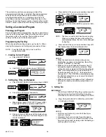
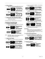
1. Clearing Current Program
a. Press SELECT PERIOD.
b. Hold CANCEL until display shows
PROG CLR.
2. Setting Day, Time, and Setpoints
a. Press SELECT PERIOD until display shows
WAKE.
b. Press DAY until display shows
MON.
c. When display reads
COOL SET PT, press HEAT/
COOL SETPOINTS to switch to
HEAT SET PT.
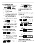
d. Press and hold a TIME key until the display shows
the desired starting time. The time changes in ten-
minute increments.
e. Press and hold the up or down arrowhead key until
the display shows the desired temperature.
f.
Press HEAT/COOL SETPOINTS to switch to
COOL
SET PT.
NOTE:
The time is used for both heating and cooling.
When you change the time while setting the
cooling temperatures, the time is also changed
for heating.
g. Press and hold the up or down arrowhead key until
the display shows the desired temperature.
NOTES:
— When the numbers do not move while you are
holding the up or down arrowhead key, the setting
limit (45°F and 88°F) is reached.
— When set for auto changeover, there must be 3°F
between the heating and cooling setpoints. When
setting the cooling setpoint with the heating setpoint
at 68°, the cooling setpoint can be no lower than 71°.
And when cooling is set for 70°, the heat setpoint
changes to 67°. The PC8900A automatically pushes
the alternate setpoint so you can adjust the setpoint
to its desired setting.
— When set for manual changeover, the 3° differential
between the heating and cooling setpoint does not
apply.
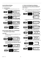
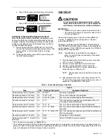
3. Setting Fan
IMPORTANT
The FAN and VENTILATOR settings are the same for
heating and cooling. The FAN setting for heating
cannot be set for AUTO and the cooling set for CIRC.
a. Press FAN until
FAN AUTO, FAN ON or FAN CIRC
is displayed, as desired.
NOTES:
— AUTO means the fan only runs when heating or
cooling is running.
— ON means the fan runs during this entire period.
— CIRC means the fan runs at least 30 percent of the
time during this period, including when the heating or
cooling system is running.
M6206
CHECK
SET
CLOCK
HEAT/COOL
SETPOINTS
SELECT
PERIOD
CANCEL
SELECT
PERIOD
HOLD
HUMIDITY
VENTILATE
RUN
SYSTEM
HEAT OFF COOL
FAN
AUTO ON CIRC
DAY
TIME
TIME
SYSTEM
WAKE
MON
HEAT SET PT COOL
M6205
CHECK
SET
CLOCK
HEAT/COOL
SETPOINTS
SELECT
PERIOD
CANCEL
CANCEL
HOLD
HUMIDITY
VENTILATE
RUN
SYSTEM
HEAT OFF COOL
FAN
AUTO ON CIRC
DAY
TIME
TIME
SYSTEM
M6206
CHECK
SET
CLOCK
HEAT/COOL
SETPOINTS
SELECT
PERIOD
CANCEL
SELECT
PERIOD
HOLD
HUMIDITY
VENTILATE
RUN
SYSTEM
HEAT OFF COOL
FAN
AUTO ON CIRC
DAY
TIME
TIME
SYSTEM
WAKE
MON
HEAT SET PT COOL
M6207
CHECK
SET
CLOCK
HEAT/COOL
SETPOINTS
SELECT
PERIOD
CANCEL
HOLD
HUMIDITY
VENTILATE
RUN
SYSTEM
HEAT OFF COOL
FAN
AUTO ON CIRC
DAY
TIME
TIME
SYSTEM
WAKE
MON
DAY
HEAT SET PT COOL
M6209
CHECK
SET
CLOCK
HEAT/COOL
SETPOINTS
HEAT/COOL
SETPOINTS
SELECT
PERIOD
CANCEL
HOLD
HUMIDITY
VENTILATE
RUN
SYSTEM
HEAT OFF COOL
FAN
AUTO ON CIRC
DAY
TIME
TIME
SYSTEM
HEAT SET PT COOL
M6215
CHECK
SET
CLOCK
HEAT/COOL
SETPOINTS
SELECT
PERIOD
CANCEL
HOLD
HUMIDITY
VENTILATE
RUN
SYSTEM
HEAT OFF COOL
FAN
AUTO ON CIRC
DAY
TIME
TIME
SYSTEM
MON
TIME
TIME
AM
M6210
CHECK
SET
CLOCK
HEAT/COOL
SETPOINTS
SELECT
PERIOD
CANCEL
HOLD
HUMIDITY
VENTILATE
RUN
SYSTEM
HEAT OFF COOL
FAN
AUTO ON CIRC
DAY
TIME
TIME
SYSTEM
AUTO
FAN
HEAT SET PT COOL
M6231
CHECK
SET
CLOCK
HEAT/COOL
SETPOINTS
HEAT/COOL
SETPOINTS
SELECT
PERIOD
CANCEL
HOLD
HUMIDITY
VENTILATE
RUN
SYSTEM
HEAT OFF COOL
FAN
AUTO ON CIRC
DAY
TIME
TIME
SYSTEM
HEAT
COOL SET PT
AUTO
FAN
WAKE
M6232
CHECK
SET
CLOCK
HEAT/COOL
SETPOINTS
SELECT
PERIOD
CANCEL
HOLD
HUMIDITY
VENTILATE
RUN
SYSTEM
HEAT OFF COOL
FAN
AUTO ON CIRC
DAY
TIME
TIME
SYSTEM
HEAT
COOL SET PT
AUTO
FAN
M6213
CHECK
SET
CLOCK
HEAT/COOL
SETPOINTS
SELECT
PERIOD
CANCEL
HOLD
HUMIDITY
VENTILATE
RUN
SYSTEM
HEAT OFF COOL
FAN
AUTO ON CIRC
DAY
TIME
TIME
SYSTEM
HEAT
COOL SET PT
WAKE
FAN
AUTO ON CIRC
AUTO
FAN


