4
D
GB
F
NL
I
E
OnCell G3150A-L
TE-EU · Edition 09.18 · GB
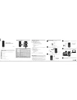
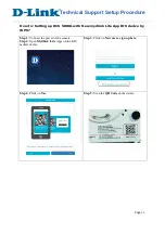
Press the OnCell G3150A-LTE towards the DIN
rail
until it snaps into place:
2
1
2
1
▷
To remove the OnCell G3150A-LTE from the DIN
rail, reverse steps
and
above.
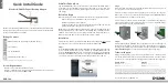
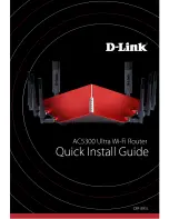
Wall Mounting (optional)
▷
Wall-Mounting Kit Dimensions:
Unit = mm (inch)
67.0 (2.64)
36.0 (1.42)
20.0 (0.79)
6.0 (0.24)
10.0
(0.39)
20.0
(0.79)
8.0
(0.32)
▷
For some applications, it may be more conveni-
ent to mount the OnCell G3150A-LTE to a wall:
Remove the aluminum DIN-rail attachment plate
from the OnCell G3150A-LTE
Then attach the wall-mounting plates with M3
screws.
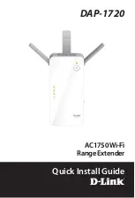
▷
Mounting the OnCell G3150A-LTE to a wall re-
quires 4 screws.
Use the OnCell G3150A-LTE device, with wall
mount plates attached as a guide, to mark the
correct locations of the 4 screws.
▷
The heads of the screws should be less than 6.0
mm in diameter, and the shafts should be less
than 3.5 mm in diameter.
< 6 mm
< 3.5 mm
▷
Test the screw head and shank size by insert-
ing the screws into one of the keyhole shaped
apertures of the wall-mounting plates before
attaching the plates to the wall.
4
Once the screws are fixed into the wall, insert
the four screw heads through the large opening
of the keyhole-shaped apertures.
5
Then slide the OnCell G3150A-LTE downwards.
6
Tighten the four screws for added stability.
Wiring
WARNING
Safety First!
Be sure to disconnect the power cord before install-
ing and/or wiring your Moxa OnCell G3150A-LTE.
EXPLOSION HAZARD!
Do not disconnect equipment unless you have
removed the power source to the equipment or
the area is known to be non-hazardous.
▷
Use separate paths to route wiring for power
and devices.
▷
If power wiring and device wiring paths must
cross, make sure the wires are perpendicular
at the intersection point.
▷
Do not run signal or communications wiring and
power wiring in the same wire conduit. To avoid
interference, wires with different signal charac-
teristics should be routed separately.