background image

LCD6000 

Installation manual 

PAGE - 3 

LCD6000_manu-inst 

Doc. M-184.1-LCD6000T-ENG Rev A.2 

NOTIFIER ITALIA 

INSTALLATION 

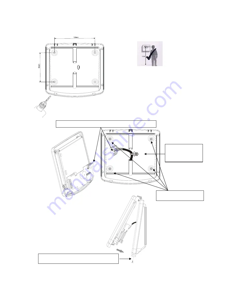
Sizes for wall assembly 


The panel can be wall- installed through 4 self-
blocking cleats (masonry walls) or self-tapping 
screws (prefabricated panels, etc.) 
The screws used must have a maximum diameter of 
5 mm. It is recommended not to install the panel 
near heat sources  (radiators, etc.)


Fastening screws max  5 mm 

Fasten the  incoming 
cable with  a cable-
fastening strip 

Connect the incoming cable to CN1 extractable terminal block  

 Screws fastening the front panel to the base    

Содержание NOTIFIER LCD6000T

Страница 1: ...LCD6000T Repeater Panel Programming And installation manual ...

Страница 2: ...ITION WITH BREAKDOWN ZONE EVENTS 7 CONDITION WITH SYSTEM BREAKDOWN EVENT 8 DISPLAY OF EXCLUDED ZONES AND POINTS 8 SENSOR 9 ZONES 9 TEST 10 LOCAL PROGRAMMING 10 ADDRESS 11 BUZZER VOLUME 11 INSTALLATION IN MULTI POINT CONFIGURATION DAISY CHAIN 12 SCREENED CABLE AND EARTH CONNECTION 12 LCD 6000T BOARD TOPOGRAPHY 13 CN1 TERMINAL BLOCK 14 ELECTRICAL FEATURES 14 PROGRAMMING OF THE MMT AND IIG4 N 15 TECH...

Страница 3: ...herefore it is essential to only use material which is guaranteed by NOTIFIER and is compatible with its own control units Please consult NOTIFIER Technical Service for any doubt This system like all solid state components may be damaged by induced electrostatic voltages handle the boards holding their edges and do not touch the electronic components An appropriate earthing connection ensures in a...

Страница 4: ...ramming to assign the peripheral address The LCD 6000T panel displays time date and personalized messages coming from AM series control units On each LCD 6000T control panel can be independently performed the functions relevant to the keys Buzzer Silencing and Alarm Reset Moreover it allows to display the event lists subdivided into Alarms breakdowns System breakdowns Technical specifications Micr...

Страница 5: ...ocking cleats masonry walls or self tapping screws prefabricated panels etc The screws used must have a maximum diameter of 5 mm It is recommended not to install the panel near heat sources radiators etc Fastening screws max 5 mm Fasten the incoming cable with a cable fastening strip Connect the incoming cable to CN1 extractable terminal block Screws fastening the front panel to the base ...

Страница 6: ...es which are programmed with Type ID TEC2 or TEC3 It is permanently lit if all Pre alarm 2 events have been recognized ALARM Red It flashes if there is at least a technological type device in un recognized Pre alarm 2 condition the AL threshold is set in the control unit on the devices which are programmed with Type ID TEC2 or TEC3 It is permanently lit if all Alarm events have been recognized BUZ...

Страница 7: ...been recognized It is permanently lit if all breakdowns have been recognized VOLTAGE Green It is permanently lit if the LCD6000 T Panel is powered Exclusion Yellow 1 For fire alarm control panel AM 2000N AM 4000N AM 6000N Lit when one point or technologic zone are excluded 2 For AM 4000G Lit when the following devices are excluded Sensor Zone Siren output Immediately activation ...

Страница 8: ... the LCD6000T panel Date Hour Alarm zone counter Breakdown zone counter System breakdown counter Excluded zone counter Icon to signal the state of the serial connection In case of anomaly on the serial connection the following state icon is displayed Icon to signal the Panel state In the state of alarm and breakdown absence there is the symbol of NOTIFIER mark In the presence of excluded points or...

Страница 9: ...in a specific zone the list zone must be scrolled until the required zone is in the display area of the first event By pressing the key the list of alarm points of the selected zone can be accessed Through the arrow keys the list of alarm devices can be scrolled Alarm zone counter Date and time of the first event of zone alarm First alarm zone Text programmed for the zone Latest alarm zone Program...

Страница 10: ...breakdown zones to display the devices in a specific zone the zone list must be scrolled until the chosen zone is in the display area of the first event By pressing the key for some seconds you can access the detailed list of the selected zone breakdown points you can scroll the failed device list Breakdown zone Text prograrmmed for Failed device S sensor M module Programmed text for the device TY...

Страница 11: ...nomalous condition at the control unit Acknowledge Outputs NB This function is enabled only for the AM4000G For acknowledge outputs activated on alarm see the following procedure 1 Press the key menu to display the following 2 select the item acknowledge output siren and press the key to access the menu System breakdown counter Date and time of the event Description of the System Breakdown ...

Страница 12: ...isplay of excluded zones and points To access the display functions of the excluded zones or points follow these instructions 6 Press the key to display the following 7 Through the arrow keys select the item Exclusion and press the key to access the menu Sensors By selecting the item Sensors and confirming the choice the following display is accessed Excluded sensor number counter Excluded zone nu...

Страница 13: ...y to return to the previous menu It indicates the displayed Exclusion event number It indicates the Excluded point total number Point indication Name assigned to the point Name of the zone assigned to the point Use the arrow keys to scroll the excluded Zone list Press the key to return to the previous menu Indication of the Excluded zone Number Zone number It indicates the displayed Exclusion even...

Страница 14: ...row keys the required item press the key to confirm the selection LOCAL PROGRAMMING Press the key from the state window and subsequently through the arrow keys select the item Local Prog and press the key to access the programming menu where the user can perform the initial configuration of the LCD 6000T panel and make possible changes The following menu is displayed Use the arrow keys to select t...

Страница 15: ...s assigned to the terminal device is unique therefore it is not possible to have several terminals with the same address Buzzer volume By selecting the item Buzzer Volume through the arrow keys and pressing the Lists key to confirm the user can program the buzzer volume in case of alarm or breakdown Test Led By selecting the item Test Led through the arrow keys and pressing the Lists key to confir...

Страница 16: ... first device on the line Continue the wiring from the first device to the subsequent one and so on Install the line end resistance 120 150 0 5W on both the control unit terminals and the terminals of the last line device The maximum admitted length from the control unit to the last device is 1 5km Use screened cable of appropriate section 9574 or 9575 Belden type AM 4000 17 24V GND EOL 120 LCD 60...

Страница 17: ...ance 120 150 0 5W on both the control unit terminals and the terminals of the last line device The maximum admitted length from the control unit to the last device is 1 5km Use screened cable of appropriate section 9574 or 9575 Belden type GND 24V AM 2000 13 EOL 120 LCD 6000T 12 7 1 2 3 4 EOL 120 23 22 LCD 6000T 1 2 3 4 5 5 6 7 6 7 GND 24V AM 4000 17 EOL 120 LCD 6000T 16 11 1 2 3 4 EOL 120 31 30 L...

Страница 18: ...tor must be connected ONLY to the end on the control unit Leave the other end unconnected and insulated A B Schermo collegare assieme le due calze dei cavi A B Schermo Connettere al telaio con un anello M5 e vite Utilizzare la posizione sul telaio più vicina al connettore Tipico collegamento dell ultima periferica Tipico collegamento alla centrale RS 485 Cable screening and earthing Technical spec...

Страница 19: ...N RS 485 serial line 2 GND Power supply input 1 24Vcc ELECTRICAL FEATURES Operating temperature 5 C 40 C Relative humidity 10 93 with no condensation Storing temperature 10 C 50 C Weight Kg 0 54 Power supply Power supply 10 30Vcc Absorption without anomalies breakdowns or alarms with display off 30 mA Absorption with anomalies breakdowns or alarms with display on and active buzzer 81 mA N B In cas...

Страница 20: ...nstallation manual LCD6000 NOTIFIER ITALIA Doc M 184 1 LCD6000T ENG Rev A 2 LCD6000_manu The following pages are related to the programming of sensor technology for the following panels AM 2000N AM 4000 AM 6000N ...

Страница 21: ...programmable by the user default P2 20 of the selected highest value of the scale An alarm threshold AL programmable by the user default AL 30 of the selected highest value of the scale Highest value of the scale refer to chapter Technological Ranges CBE equation which is activated when the value detected by the device is higher than one the three thresholds CBE active OR P1 P2 AL This CBE is used...

Страница 22: ...00T display The Reset procedure must be performed for all signallings on the LCD 6000T The diagram in the figure shows the operation feature of a TEC3 device programmed with threshold inversion option NO As you can see the operation feature is to increase the current values Therefore the thresholds must satisfy the following rule P1 P2 AL It can be used for esplosive gas detection sensors 20mA 4mA...

Страница 23: ...Tracking option By enabling the tracking option when the device exceeds the alarm threshold the control unit activates the following indications Output modules associated through CBE Active Buzzer on LCD 6000T Indication of the device on the LCD 6000T display When the device returns to its normal status the output modules associated through CBE return idle while the following signallings are still...

Страница 24: ... select a new device use the function keys TEC3 programming First folder or Main folder Progr of Type ID and reading associated with the sensor S Se ec co on nd d f fo ol ld de er r o or r P Pr ro og gr ra am m f fo ol ld de er r P Pr ro og gr r o of f C CB BE E E Eq qu ua at ti io on n Z Zo on ne e a as ss so oc ci ia at ti io on n T Th hi ir rd d f fo ol ld de er r o or r O Op pt ti io on n f fo...

Страница 25: ...ult datum of the relative sensitivity Threshold sending Configuration of the operation feature refer to previous paragraph Pre alarm 1 threshold Programming The default value is 10 of the selected highest value of the scale The Pre alarm 2 threshold Programming The default value is 20 of the selected highest values of the scale The alarm threshold Programming The default value is 0 of the selected...

Страница 26: ... d L Le ed d B Bl li in nk k e et tc c Sensor address CBE equation usable to activate the generic groups Associated zone number By selecting NO in the Led Blink function the flashing of led on the module is disabled during the line query This function can be useful in such environment as hospitals hotels etc Tracking option Range Configuration of the highest value of the scale Attention don not ch...

Страница 27: ... e d de ev vi ic ce es s o of f t th he e s sa am me e l li in ne e w wh hi ic ch h h ha av ve e c co on ns se ec cu ut ti iv ve e a ad dd dr re es ss se es s a an nd d h ha av ve e c co om mm mo on n p pa ar ra am me et te er rs s The procedure to perform the block programming is the following Select a device from which the parameters are to be copied Type ID CBE etc Perform the Copy command to s...

Страница 28: ...928 10 70 C I08 I09 I10 I11 I12 I13 I14 I15 I16 The Technological Range defines the physical value that the 4 20ma interface module must analyze by assigning them the lowest values and the highest value of the scale Programming of the TECHNOLOGICAL RANGES from I08 to I16 From the Programming menu by selecting the item TECHNOLOGICAL RANGES the programming procedure is accessed First folder or Main ...

Страница 29: ... or interval folder Prog of Lowest value of the scale highest value of the scale Programming of the lowest value of the scale Enter the value indicated on the plate values of the technological device Programming of the highest value of the Scale Enter the value indicated on the plate value of the technological device ...

Страница 30: ...55 696706 Fax 055 6529294 00118 Roma Via Del Casale Santarelli 51 Tel 06 7988021 Fax 06 79880250 E mail notifier roma notifier it 80143 Napoli Via G Porzio 4 Centro Direzionale Isola E2 Scala B Piano 5 int 19 Tel 081 7879398 Fax 081 7879159 E mail notifier napoli notifier it 70125 Bari Via Della Costituente 29 Tel 080 5013247 Fax 080 5648114 E mail notifier bari notifier it 95126 Catania Via Alcid...

Отзывы: