Honeywell NOTIFIER ID2000 Series Скачать руководство пользователя страница 41

ID2000 Series Operating Manual

Operator 

Actions at Panel

38

997-434-000-4, Issue 4
May 2010

4.11 Setting the Clock

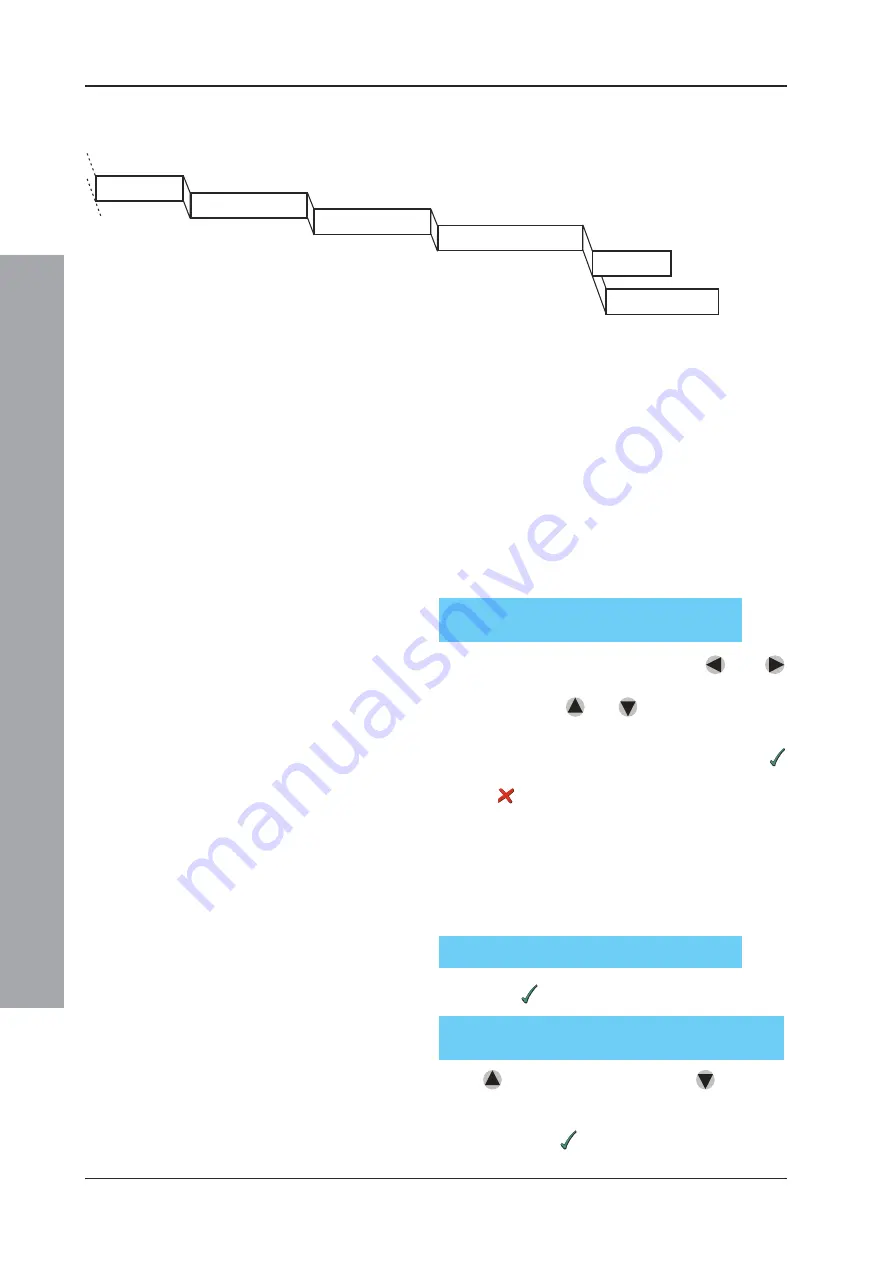
This procedure uses the LCD menus.  The menu
structure is shown below:

This operation is required after any Time Zone change,
e.g. start/end of British Summer Time if not configured
for auto-adjust, and after the system has been fully
powered-off (in the latter case the system will start-up at
midnight on the last date on which it had been operating,
or at the time when the clock was last reset, whichever
was the later).

To set the clock:

1

From the Top Level display, press Pushbutton ‘3’. The
clock display will be ‘frozen’, and will be as shown
below with the ‘seconds’ part of the ‘time’ field of the
clock flashing on the display:

To adjust the date and time, use the 

 and 

pushbuttons to move the cursor over the field to be

changed.  Use the 

 and 

 pushbuttons to adjust

the value of the field to give the current date and time.

2

After all fields have been adjusted correctly, press 
to start the clock running at the precise time shown,
or press 

 to cancel the whole operation and return

to the previous clock setting.

If the panel status is ENGINEER (i.e. the access 3
passcode has been entered), the following additional
steps are provided before the clock is started:

a. Adjust clock speed.  The following is displayed:

If you press 

, the display is:

Press 

 to make the clock go faster, 

 to make it

go slower (to determine the value to enter, measure
the increase or decrease in clock time over the course
of a week). Press 

 to end the adjustment.

SETTING CLOCK (date) (time)

Use 

<−

<−

<−

<−

<−


↑↓ −>

↑↓ −>

↑↓ −>

↑↓ −>

↑↓ −>

 to adjust, 

!

!

!

!

!

 to end

Setting Clock menu structure. The
available menus within this structure
depend upon the passcode and the panel
configuration.

Adjust Clock Speed (

!

!

!

!

!

/X)?

CLOCK to run 

(FASTER)(SLOWER)

 by n.n seconds

per week (use 

↑↓

↑↓

↑↓

↑↓

↑↓

)

SETTING CLOCK

SETTING CLOCK

SET NEW DATE/TIME

SET NEW DATE/TIME

ADJUST CLOCK SPEED

ADJUST CLOCK SPEED

SET SUMMER TIME START/END

SET SUMMER TIME START/END

START CLOCK

CANCEL CLOCK RESET

CANCEL CLOCK RESET

Содержание NOTIFIER ID2000 Series

Страница 1: ...ID2000 operating manual 997 434 000 4 Issue 4 May 2010 ...

Страница 2: ...te Buzzer 9 4 3 Accept 10 4 4 Evacuate 11 4 5 Silence and Re start Sounders 12 4 6 Reset 12 4 7 Lamp Test and Display Control 13 4 7 1 Lamps Test In Sequence 13 4 7 2 All Lamps Lit and LCD Adjust 13 4 8 System Test 14 4 8 1 Zone Walk Test 16 4 8 2 Control Output Test 18 4 8 3 Sensor Automatic Test 20 4 8 4 Replace VIEW Sensor 21 4 9 Disablement and Enablement 23 4 9 1 Individual Device 25 4 9 2 Co...

Страница 3: ...e 4 May 2010 4 10 2Print Device Data 34 4 10 3Display and Re Print Event Log 36 4 10 4Printer Control Modes 37 4 11 Setting the Clock 38 4 12 Select Day or Night Mode 39 4 13 Set Language 39 5 Non latched Input Operation 40 APPENDIX 1 Status Summary A1 1 to A1 12 ...

Страница 4: ...lation or configuration of ID2000 Series panels For information on these topics refer to the ID2000 Series Installation and Commissioning Manual 997 433 XXX and the ID2000 Series Panel Configuration Manual 997 435 XXX respectively Note XXX is the country code for the manual 000 for the UK 1 2 The ID2000 Panels The ID2000 Series is a very powerful and versatile range of Fire Alarm panels which may ...

Страница 5: ...hen these sensors are installed or replaced see Section 4 8 4 All panels have a powerful CONTROL MATRIX feature This is a set of logic instructions stored in the panel s internal software It determines exactly which control outputs sounders etc are to operate on the occurrence of any specific Fire Alarm input and in what manner Examples of the large range of options that may be configured in a par...

Страница 6: ...BLE TEST LEDs indicate affected zone s Status LEDs DISABLEMENT PRE ALARM REMOTE OUTPUT DISABLED TEST SOUNDERS DISABLED REMOTE OUTPUT FAULT EARTH FAULT SOUNDER FAULT REMOTE OUTPUT OPERATED POWER SUPPLY FAULT DELAY ACTIVE SYSTEM FAULT DAY MODE POWER 7 8 9 4 5 6 1 2 3 0 1 9 5 13 3 11 7 15 2 10 6 14 4 12 8 16 MUTE BUZZER MUTE BUZZER ACCEPT SILENCE SOUNDERS SILENCE SOUNDERS RESOUND SOUNDERS RESOUND SOU...

Страница 7: ...nces Point information on pre alarms may be accessed at the LCD but are suppressed by the fire event information Recommended operator actions 1 Press theACCEPTpushbutton More information about the alarm appears on the display Flashing lamps changetosteadyoperation Theinternalbuzzerchanges to intermittent operation once every 12 seconds 2 Follow prescribed instructions for evacuation of premises no...

Страница 8: ...ssociated with pre alarm events if there are any specified in the Control Matrix configuration d Display and printing if printer is installed and enabled of the event Recommended operator actions 1 Press the ACCEPT pushbutton The internal buzzer changes to intermittent operation once every 2 minutes More information about the pre alarm appears on the display Flashing PRE ALARM lamp changes to stea...

Страница 9: ...y for automatic alert to a service centre Recommended operator actions 1 Press the ACCEPT pushbutton More information about the fault appears on the display Flashing lamps change to steady operation The internal fault sounder changes to intermittent operation once every 2 minutes 2 If the fault relates to a specific sensor or module investigate device to see if cause of fault is immediately appare...

Страница 10: ...verride delay to outputs if delay is active d Silence and re start the alarms e Reset the panel f Test the lamps and control the LCD display contrast g Carry out system tests h Disable and enable devices zones or all outputs i Display log and print data j Set the time of day clock k Select Day or Night Mode for remote fire outputs l Set the language displayed on the LCD All of these actions are se...

Страница 11: ...s of the state of the display but will not display the top level menu if the panel is asking for a response b The main controls MUTE BUZZER ACCEPT EVACUATE SILENCE SOUNDERS RESOUND SOUNDERS and RESET may also be pressed at any time Anyoperatoractioninprogressatthetimeisaborted If no key is pressed for 2 minutes 20 seconds after pressing ACCEPT the system automatically reverts back to the Top Level...

Страница 12: ... status indication in the absence of any alarms faults or masked devices will show ENGINEER During this time the passcode need not be re entered for further operations which require it To cancel the ENGINEER status and thus prevent any other person from access for which a passcode is required press the pushbutton from the Top Level display Note The panel automatically carries out this cancellation...

Страница 13: ...button was pressed you may step through the events by i Operating the up or down arrow keys to go backwards or forwards in time respectively MORE appears on the text display to indicate further events ii Press to revert to the top level display if no key is pressed within 20 seconds the system reverts to the Top Level display automatically d TheACCEPT pushbutton may be pressed at any time in order...

Страница 14: ...Press A WAIT message is displayed momentarily until the sounders operate No further action is needed until it is required to silence the sounders in which case SILENCE SOUNDERS should be pressed If the panel is configured with a delay to outputs then pressing EVACUATE while the delay is active will override the delay and immediately activate the output If the EVACUATE pushbutton is pressed while t...

Страница 15: ...ttern as they were previously operating press the RESOUND SOUNDERS pushbutton Note RESOUND SOUNDERS works for a fire condition only not for an operation of the EVACUATE pushbutton Note When the sounders are restarted the internal fire sounder will also change back to steady mode of operation and you may have to press MUTE BUZZER again 4 6 Reset To reset the system completely except after an EVACUA...

Страница 16: ...s from its outer edges to the centre This verifies that every pixel on the display is switching on and off correctly 4 7 2 All Lamps Lit and LCD Adjust To switch all lamps on until cancelled and adjust the LCD display 1 With the TEST menu displayed hold the 2 pushbutton down for approximately 3 seconds The following is displayed 2 Press all the lamps will be switched on and will remain on until or...

Страница 17: ... individual CONTROL OUTPUT TEST c Perform a LAMP TEST see Section 4 7 Additional options may be available depending upon the configuration of the panel The option numbers vary depending upon how many options are available d Perform a SENSOR AUTOMATIC TEST e Perform a REPLACE VIEW SENSOR operation Example TEST menus are shown below TEST 0 Zone 1 Output 2 Lamps TEST 0 Zone 1 Output 2 Lamps 3 Replace...

Страница 18: ...ed after replacement select the appropriate pushbutton and see Section 4 8 4 TEST ZONE WALK TEST ZONE WALK TEST CONTROL OUTPUT TEST SENSOR AUTOMATIC TEST REPLACE SENSOR REPLACE SENSOR TEST MODE NETWORKED PANEL TEST MODE NETWORKED PANEL TEST MODE STAND ALONE PANEL TEST MODE STAND ALONE PANEL CANCEL TEST MODE CANCEL TEST MODE CMX MODULES CMX MODULES SOUNDER 1 SOUNDER 1 SOUNDER 3 SOUNDER 3 SOUNDER 2 ...

Страница 19: ...ress The panel applies a remote automatic fire simulation control to each of the sensors in the selected zone and verifies that each sensor responds correctly This stage of the test lasts a few seconds during which only failures registered for this test are reported 2 The display subsequently shows where n is the zone number The corresponding zone FAULT lamp illuminates steady The panel TEST lamp ...

Страница 20: ... number of times test alarms are auto resetting Wait at least 5 seconds before re testing a device To cancel testing 1 Press The following is displayed for a short time only 2 From the above display press pushbutton 0 to display the TEST menu once more Again press the 0 pushbutton to select Zone The display will be 3 Press and the system returns to normal operation This action must be carried out ...

Страница 21: ...able a scan through all zones The panel display is then 3 Either a Press or both these keys auto repeat if held down until details of the module you want are shown then press The module can only be one which is present on the system note that existing devices need not be numbered consecutively If while scanning up or down you press neither arrow key for a second or two the module location text if ...

Страница 22: ...le you will have to repeat the above sequence and press to stop the test 4 8 2 2 Local Sounder Circuits To test one of the four local sounder circuits 1 Press 1 2 3 or 4 in response to the options shown in Section 4 8 2 The system displays one of the questions shown below depending upon whether the sounder is currently active or not 2 Press to perform the test To switch off the sounder quickly sim...

Страница 23: ...a fault is detected There is normally no need to force the panel to undergo this test ahead of the scheduled time but if you need to do so 1 Press the 0 pushbutton as detailed in Section 4 8 followed by the appropriate pushbutton to select the Auto test NOW option One of the following is displayed depending upon what interval is configured in the panel 2 Press to start the test The panel will reve...

Страница 24: ... exposed to smoke or other abnormal conditions otherwise the panel may report a sensor fault The Replace Sensor menu option refers only to the VIEW sensor If a VIEW sensor is removed from an existing operational loop or communication with the panel is broken for a minimum of 30 seconds recalibration will take place automatically Note If a VIEW sensor is removed and cleaned or replaced with a new o...

Страница 25: ...action is logged and if a printer is installed the message sensor replaced is printed out 4 8 4 2 Loop of VIEW Sensors To recalibrate a loop of VIEW sensors 1 Press 1 The panel displays the prompt shown below 2 Enter the loop number The panel then displays one of the prompts shown below depending upon whether ALL loops or a single loop is specified 3 Press to complete the operation Sensors will be...

Страница 26: ...f the Control Matrix specifies that it is required to do so There is normally no time out for disabled devices the disablement is effectively permanent until cancelled by a subsequent enablement operation Some systems however may be configured so that disablement see Section 4 9 1 is automatically cancelled after a set time out or at certain times of the day non EN54 compliant See the ID2000 Serie...

Страница 27: ...dividual device b Disable Enable a complete zone c Disable Enable outputs These modes are described in detail in the following sections All operations use the LCD display menu the structure of which is shown below Disablement and enablement menu structure The available menus within this structure depend upon the passcode and the panel configuration ...

Страница 28: ...sing the same procedure as described for the Control Output Test in Section 4 8 2 1 When you have found the device you want press Note If the device selected is in a zone which has previously been disabled by means of a remote switch the system displays this warning message Enter a passcode to override the remote switch action if you have already entered a passcode for a previous operation you are...

Страница 29: ... zone selecting a number greater than 80 and less than 256 allows a cell to be disabled in the same way as a zone Note If you select a zone which has previously been disabled by means of a remote switch the system displays this warning message Enter a passcode to override the remote switch action if you have already entered a passcode for some previous operation you are simply asked to confirm you...

Страница 30: ...ling local zones there is no option to specify whether sensors all inputs or input and outputs are to be included That is determined by the configuration of the Slave panel which you have selected Note This facility can be initiated only at the Master panel unlike the REMOTE TEST facility described in Section 4 8 1 which can be initiated at any panel on the network 4 9 3 Outputs To disable or enab...

Страница 31: ...h has been configured as an AUXILIARY type input and this has been linked to a DISABLE operation on a particular zone or zones See the ID2000 Series Panel Configuration Manual 997 435 XXX for details on how to configure this option The function enables the use of a remotely placed switch to disable and enable zones without the need for access to the panel Only complete zone disablement not that of...

Страница 32: ...4 All operations use the LCD display menu the structure of which is shown below Log Display menu structure The available menus within this structure depend upon the passcode and the panel configuration LOG DISPLAY DEVICES DISPLAY PRINT ZONE ZONE SENSOR MODULE NOT LOGGED NOT LOGGED LOGGED ENTER LOGGING DETAILS ENTER LOGGING DETAILS SENSORS MODULES ZONE BY VALUE THRESHOLD DISABLED DEVICES DISABLED D...

Страница 33: ...et up a memory log of its data readout See below for details To display and or log device data 1 From the top level display press pushbutton 2 on the VDU press 8 If operating from the panel the options shown below are displayed 2 Select option 0 This step is omitted if operating from the VDU The options shown below are then displayed 3 Select option 0 The options shown below are then displayed 4 P...

Страница 34: ...nning up or down you press neither arrow key for a second or two the device location text if programmed also appears 8 Press again to finally select the device Then in place of the location text line 2 of the display shows one of the two messages shown below The value is continuously updated The LOGGED message indicated whether a memory log is currently set up for that sensor at start up all devic...

Страница 35: ...y stop this by repeating the above procedure in this case the question shown below is asked Alternatively press RESET b Logging facility This applies only to analogue sensors and allows the data reading from the device to be stored in memory at regular time intervals It is intended for use in conjunction with the ID2000 Series support tool which runs on an IBM compatible personal computer This pro...

Страница 36: ...lculate the total logging period multiply this by the Interval already entered The prompt shown below is then displayed Press to complete the set up or to cancel the whole procedure Note The maximum store capacity depends on the available memory If another sensor is already being logged less than the maximum of 4000 values may be available Up to 22 sensors may be logged simultaneously with a combi...

Страница 37: ...rs and Modules must be printed out as separate operations 5 If required select a zone The display is as shown below Either key in the specific Zone number followed by to print only the devices in that zone or just to select the default of ALL ZONES 6 If ALL ZONES is selected the question shown below is displayed This allows selective printing of only those devices with an unusually high reading Ei...

Страница 38: ...system any disabled devices connected to the Slave panels are also printed this is the only case in which a list of devices at another panel can be obtained The printout will list in addition to configuration details about each device and its current reading indications of any device that is disabled and any device that is MISSING i e registering a NO REPLY fault To abort the printout Press on the...

Страница 39: ...ded such events have not been over written by more recent events press The question shown below is then displayed The date and time fields initially show the date and time now not that of the most recent event The date field will be flashing 4 Press repeatedly to step back a day at a time and to step forward You cannot select a date later than today nor earlier than the oldest event still recorded...

Страница 40: ...t event you want re printed using the same method as described above If you press twice without changing anything re printing is carried out all the way up to the present time Note When any portion of the event history is re printed the original sequence numbers of the re printed events are also reproduced This enables you to determine on inspecting the printout where the re printed data ends and ...

Страница 41: ...eld to give the current date and time 2 After all fields have been adjusted correctly press to start the clock running at the precise time shown or press to cancel the whole operation and return to the previous clock setting If the panel status is ENGINEER i e the access 3 passcode has been entered the following additional steps are provided before the clock is started a Adjust clock speed The fol...

Страница 42: ...splayed Enter the passcode and press pushbutton Select the appropriate option The LCD returns to the Top Level display If Day Mode was selected the DISABLEMENT and DAY MODE LEDs light and System in DAY mode is displayed on the LCD If an alarm occurs during DAY MODE the DAY MODE LED flashes and the first investigation time begins delaying activation of the remote fire outputs Press ACCEPT during th...

Страница 43: ... Panel Configuration Manual 997 435 XXX for details on how to configure this option Operate the switch as indicated to cause the sounders or other outputs to operate in the pre programmed pattern Release the switch to switch off the outputs Normally there will be no indication at the panel of these operations However some installations may be configured so that the text display shows the last such...

Страница 44: ...ons for each status condition The default status is quiescent or NORMAL which indicates the absence of any other condition The other conditions are exceptions and more than one at a time may be present The following list is in order of the priority of indications on the panel display a EXTINGUISHANT RELEASE b FIRE c PRE ALARM d FAULT e DEVICE S DISABLED f EVACUATE g TEST h ENGINEER i ENGINEER S MU...

Страница 45: ...ary action The built in LED indicators on all sensors and modules should either give short pulses or be off altogether The system normal message is a text message specially customised for your installation and may consist of an advertisement such as the building name or similar information Note The MUTE BUZZER ACCEPT EVACUATE SILENCE SOUNDERS RESOUND SOUNDERS and RESET pushbuttons each have an ass...

Страница 46: ... if accepted STEADY If a new alarm occurs flashes again until accepted Numbered zone indication s for zone s where Fires have been detected red if not accepted FLASHING if accepted STEADY The LCD display is as shown below For approximately two minutes after an Alarm is accepted line 2 shows a scrollable message use and to scroll giving full details about the occurrence FIRE Device number zone type...

Страница 47: ...NDERS pressed some or all devices may now be OFF dependent upon programming The built in LED indicators on the sensor s and or module s which issued the alarm will either be on STEADY if the alarm input conditions e g presence of smoke still exist or show 1 second on 1 second off pulses possibly with intervening short pulses if the alarm input conditions are no longer present e g smoke has now cle...

Страница 48: ...ws LAMP indications POWER green ON PRE ALARM LAMP amber if not accepted FLASHING if accepted STEADY All other LAMPs OFF The LCD displays the message shown below For approximately two minutes after a Pre Alarm is accepted line 2 shows a scrollable message use and to scroll giving full details about the occurrence PRE ALARM Device number zone type analogue value at time of alarm location date time o...

Страница 49: ...T pushbutton if so the status is still FAULT The indications of the panel and external equipment are as follows LAMP indications POWER green if mains or battery power OK ON EARTH FAULT POWER SUPPLY FAULT SYSTEM FAULT LAMP amber as appropriate if not accepted FLASHING if accepted STEADY Numbered zone indication s for zone s where sensor module faults have been detected amber if not accepted FLASHIN...

Страница 50: ...ounder Circuits Programmed Function FIRE relay OFF FAULT relay ON External Devices All CONTROL MODULES should be Programmed Function For certain types of fault TYPE MISMATCH and DUPLICATE ADDRESS the built in LED indicators on the sensor s and or module s for which the fault occurred will show 1 second ON 1 second OFF pulses possibly with intervening short pulses The built in LED indicators on all...

Страница 51: ... a higher priority condition or until cleared by removing all devices from a disablement status If an Alarm or Fault occurs and is subsequently cleared and RESET is pressed then if appropriate the panel reverts to showing the DEVICES DISABLED status The LCD displays the message shown below The indications of the panel and external equipment are as follows LAMP indications POWER green ON DISABLEMEN...

Страница 52: ...ndications POWER green ON All others OFF Internal sounders OFF Circuits Controlled Internally Sounder Circuits if not substituted by alternative devices in matrix program both circuits on STEADY FIRE FAULT relays OFF External Devices depending on programmed EVACUATE schedule some or all Control modules may be ON either steady or pulsing The LEDs of active Control Modules those for which the contro...

Страница 53: ...w The indications of the panel and external equipment are as follows LAMP indications POWER green ON TEST amber ON All other LAMPs OFF Numbered zone indication amber STEADY Internal sounders and Circuits Controlled Internally as for status NORMAL External Devices All CONTROL MODULES should be OFF The built in LED indicators on the sensor s in the Zone in test show 1 second ON 1 second OFF pulses p...

Страница 54: ...the panel and external equipment are as follows All other indications and external equipment as for status NORMAL PANEL STATUS ENGINEER MUTE This is functionally identical to the NORMAL status except that a special option has been selected by the authorised engineer to partially inhibit the functioning of the fault buzzer Operation of the FIRE internal buzzer is not affected This mode is normally ...

Страница 55: ...tion therein Design features may be changed or amended without prior notice Quality Systems Certificate No 154 Assessed to ISO9001 L O S S P R E V E N T ION CERTIFI C A T I O N B O A R D 007 Charles Avenue Burgess Hill W Sussex RH15 9UF T 44 0 1444 230 300 F 44 0 1444 230 888 E sales notifierfiresystems co uk www notifierfiresystems co uk ...

Отзывы: