Honeywell NFS-3030 Скачать руководство пользователя страница 43

Notifier SLC Wiring Manual —

 P/N 51253:U5 12/20/2017

43

Connecting a Releasing Device to the Addressable Control Module

Control Modules

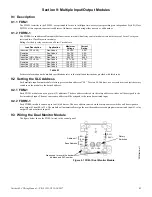
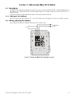
7.5  Connecting a Releasing Device to the Addressable Control Module

The FCM-1-REL module can control 1 A of current. Make sure to keep total system current within the limits of the power supply. Power 
for the module must come from the FACP’s main power supply or any UL 864-listed 24 VDC regulated, power-limited power supply for 

Fire Protective Signaling. For more information, refer to the 

Device Compatibility Document

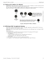
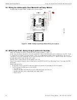
Figure 7.6 shows Class B wiring of the FCM-1-REL.    

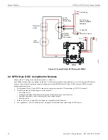
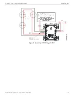
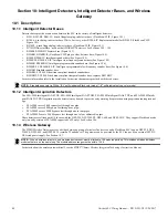
Figure 7.7 shows Class A wiring of the FCM-1-REL.

Critical Requirements.
When connecting a releasing device to the FCM-1-REL module, note the following:

1.

See “Power Considerations” on page 58 for information on monitoring 24 VDC power.

2.

Do not T-tap or branch a Style Y or Style Z circuit.

3.

Only one (1) 24V solenoid or two (2) 12V solenoids in series can be connected to the FCM-1-REL.

4.

Do not loop wiring under the screw terminals. Break the wire run to provide supervision of connections.

5.

All applications using the FCM-1-REL are power-limited:
• Program the releasing circuit for Type Code REL CKT ULC or RELEASE CKT.
• Circuits are supervised against opens and shorts.

6.

Refer to your FACP’s listing documents for instructions on setting the Soak Timer. 

(* For legacy panels, refer to FACP programming manual.) 

7.

The FCM-1-REL module must be programmed with the correct releasing type code listed in your FACP’s listing documents. 

(* For legacy panels, refer to FACP programming manual.) 

T11

T10

T9

T1

TENS

ONES

LOOP

ADDRESS

Module polarities are shown in alarm 
condition. All wiring shown is 
supervised and power-limited.

Compatible UL-listed 
24 VDC releasing device. 
One (1) device maximum.

Non-resettable 24-VDC power 
supply isolated, regulated, power 
limited per NFPA 70, listed for fire 
protection with battery backup.

When using the 
FCM-1-REL for 
Class B 
applications, 
remove jumper J1.

SLC (-)

SLC (+)

Figure 7.6  NFPA Class B Wiring of the FCM-1-REL

m

30

0c

j-

re

ly

.w

m

f

FCM-1-REL

T11

T10

T9

T1

TENS

ONES

LOOP

ADDRESS

Non-resettable 24-VDC power 
supply isolated, regulated, power 
limited per NFPA 70, listed for fire 
protection with battery backup.

SLC (-)
SLC (+)

Compatible UL-listed 
24 VDC releasing device. 
One (1) device maximum.

Module polarities are shown in alarm 
condition. All wiring shown is 
supervised and power-limited.

Figure 7.7  NFPA Class A Wiring of the FCM-1-REL

FCM-1-REL

Содержание NFS-3030

Страница 1: ...Intelligent Control Panel SLC Wiring Manual Document 51253 Rev U5 12 20 2017 ECN 17 0433 ...

Страница 2: ... provide adequate warning of a fire Smoke detectors cannot be expected to provide adequate warning of fires caused by arson children playing with matches especially in bedrooms smoking in bed and violent explosions caused by escaping gas improper storage of flammable materials etc Heat detectors do not sense particles of combustion and alarm only when heat on their sensors increases at a predeterm...

Страница 3: ...ove all electronic assemblies prior to any drilling filing reaming or punching of the enclosure When possible make all cable entries from the sides or rear Before making modifications verify that they will not interfere with battery transformer or printed circuit board location Do not tighten screw terminals more than 9 in lbs Over tighten ing may damage threads resulting in reduced terminal conta...

Страница 4: ...priate version for a specific application Documentation Feedback Your feedback helps us keep our documentation up to date and accurate If you have any comments or suggestions about our online Help or printed manuals you can email us Please include the following information Product name and version number if applicable Printed manual or online Help Topic Title for online Help Page number for printe...

Страница 5: ...ing Requirements 16 2 1 Recommended SLC Wiring 16 2 2 Two Wire SLC Style 4 Class B 17 2 2 1 Measuring Loop Resistance 17 2 2 2 Measuring Total Wire Length 18 2 3 Four Wire SLC Style 6 7 Class A 18 2 3 1 Measuring Loop Resistance 18 2 3 2 Measuring Total Wire Length 19 2 4 Control Panel Terminal Blocks 19 2 4 1 NFS2 3030 and NFS 3030 with LCM 320 LEM 320 19 2 4 2 NFS2 640 with Loop Expander Modules...

Страница 6: ...e Relay Module Form C Relay 44 Section 9 Multiple Input Output Modules 45 9 1 Description 45 9 1 1 FDM 1 45 9 1 2 FDRM 1 45 9 2 Setting the SLC Address 45 9 2 1 FDM 1 45 9 2 2 FDRM 1 45 9 3 Wiring the Dual Monitor Module 45 9 4 Wiring the Addressable Dual Monitor Dual Relay Module 46 9 5 NFPA Style B IDC Wiring Using Dual Monitor Modules 46 Section 10 Intelligent Detectors Intelligent Detector Bas...

Страница 7: ...0 LIB 200A or LIB 400 64 B 2 4 NFS2 3030 NFS 3030 NFS2 640 NFS 640 NFS 320 and NFS 320SYS 65 Appendix C Terminal Conversion Charts for V type and H type Devices 67 C 1 FRM 1 67 C 2 FCM 1 and FZM 1 68 C 3 FMM 1 68 C 4 FTM 1 68 C 5 FDM 1 69 Appendix D Intelligent Detector Base Layouts for Legacy Devices 70 D 1 Wiring a Detector Base 70 D 2 Wiring an Isolator Base 71 D 3 Wiring a Relay Base 71 D 4 Wi...

Страница 8: ...ix C has been provided for those who need that wiring information it contains terminal conversion charts between the old and new formats In this appendix the modules are referred to as h type the new format which has horizontal rotary dials and v type the old format which has vertical rotary dials This naming convention is a convenient way to avoid confusion when referring to a particular model as...

Страница 9: ... and Programming Manuals 50253 50259 50260 System 5000 with AIM 200 Refer to the AIM 200 Manual 15949 System 5000 Installation Operations and Programming Manuals 15583 15581 15584 AM2020 AFP1010 Installation Manual 15088 NFS 640 Installation Operations and Programming Manuals 51332 51334 51333 NFS 3030 FACP Installation Operations and Programming Manuals 51330 51345 51344 NFS 320 and NFS 320SYS UL...

Страница 10: ...intelligent non relay low flow photoelectric duct detector housing DNRA Canadian I56 3051 I56 3104 FAPT 751 Acclimate Plus Multi Sensor Detector Installation Document Replaced by FAPT 851 FAPT 851 See document for FSP 851 FSP 851T and FAPT 851 FAPT 851A See document for FSP 851A FSP 851TA and FAPT 851A I56 3524 I56 2296 FCM 1 Control Module Installation Document FCM 1A Canadian I56 1169 I56 3500 F...

Страница 11: ... 951R and FSP 951R IV Intelligent Photo Smoke w Remote Test Capability FSP 951RA and FSP 951RA IV Canadian I56 6520 I56 2231 FSP 951T and FSP 951T IV Intelligent Photo Temperature Detector FSP 951TA and FSP 951TA IV Canadian I56 6521 I56 2232 FST 951 IV FST 951R IV FST 951H IV Intelligent Heat Detector FST 951A IV FST 951RA IV FST 951HA IV Canadian I56 6522 I56 2233 FST 751R Rate of Rise Sensor In...

Страница 12: ...ng in degraded mode where supported by the FACP See the XP5 Series Manual XP6 MA Allows an intelligent alarm system to monitor six zones of conventional two wire detectors FlashScan or CLIP mode XP10 M Supervises ten Class B addressable Initiating Device Circuits IDC which monitor normally open contact initiating devices FlashScan or CLIP mode This module is capable of participating in degraded mo...

Страница 13: ... the B200S B200SR LF A low frequency version of the B200SR Relay Base B224RB B224RB IV 1 6 8 Intelligent Detectors FCO 851 IntelliQuad PLUS Intelligent Photoelectric Multi Criteria Smoke CO Carbon Monoxide detector Plug in type smoke sensor that is a photoelectric sensing chamber combined with Carbon Monoxide CO thermal and infra red IR sensors to help reduce false alarms For CO the detectors elec...

Страница 14: ... FSA 8000 Intelligent FAAST XM aspiration smoke detector Covers 8 000 square feet through one pipe Supports FlashScan and CLIP mode An earlier model was CLIP mode only Compatible with NFS 320 NFS 320SYS NFS2 640 and NFS2 3030 only Addressed using PipeIQ software FSA 20000 Intelligent FAAST XT aspiration smoke detector Covers 28 800 square feet through one to four pipes Supports FlashS can and CLIP...

Страница 15: ...Trouble Single Ground Alarm Trouble ground Alarm Trouble ground Alarm Trouble ground Short Trouble Trouble Alarm Trouble Short and open Trouble Trouble Trouble Short and ground Trouble Trouble Alarm Trouble Open and ground Trouble Alarm Trouble Alarm Trouble Communications loss Trouble Trouble Trouble Trouble The control panel will indicate a trouble condition for this type of fault Alarm The cont...

Страница 16: ...nduit or outside of conduit 1 000 ft 304 8 m 12 to 18 AWG 3 31 mm to 0 82 mm Note Twisted shielded pair is not recommended for use with this panel Note Maximum total capacitance of all SLC wiring both between conductors and from any conductor to ground should not exceed 0 5 microfarads NFS 320 NFS 320SYS NFS2 640 LEM 320 on NFS2 640 LCM 320 LEM 320 on NFS 3030 NFS2 3030 RECOMMENDED Twisted unshiel...

Страница 17: ...s AFP 300 AFP 400 Twisted shielded pair 12 to 18 AWG 40 ohms maximum per length of Style 6 and 7 loops 40 ohms per branch maximum for Style 4 loops 10 000 ft 3 048 m 8 000 ft 2 438 4 m 4 875 ft 1 485 9 m 3 225 ft 982 98 m 12 AWG 3 31 mm 14 AWG 2 08 mm 16 AWG 1 31 mm 18 AWG 0 82 mm Untwisted unshielded wire in conduit or outside of conduit 1 000 ft 304 8 m 12 to 18 AWG 3 31 mm to 0 82 mm Note Twist...

Страница 18: ...r exceed 50 ohms for NFS 320 NFS2 640 NFS 640 LCM 320 LEM 320 LIB 200A and LIB 400 40 ohms for AFP 100 AFP 200 AFP 300 400 LIB 200 AIM 200 Measure DC resistance as detailed and shown below 1 Disconnect the SLC channel B Out and SLC channel A Return at the control panel 2 Short the SLC at the last device and measure the resistance at SLC Out Record resistance and remove the short Refer to Figure 2 ...

Страница 19: ...five pairs of loop control and expander modules providing from one to ten SLC loops Loops can be either CLIP mode or FlashScan mode SLC loops connect to TB1 on the LCM 320 or LEM 320 SLC meas5 wmf SLC Out SLC Return Short Point SLC Return SLC Out STEP 2 STEP 3 First Device Last Device Last Device First Device Figure 2 3 Measuring DC Resistance of a Four Wire SLC B A B A SLC channel B output loop S...

Страница 20: ...shScan mode SLC loop 1 connects to TB16 on the control panel SLC loop 2 connects to TB1 on the LEM 320 2 4 4 AFP 100 The AFP 100 supports one SLC loop the loop is CLIP mode only The SLC loop connects to TB6 2 4 5 AFP 200 The AFP 200 supports one SLC loop the loop is CLIP mode only The SLC loop connects to TB5 SLC Loop 2 Connections on Loop Expander Module SLC Loop 1 Connections on FACP s main circ...

Страница 21: ...e only The SLC loop connects to P8 on AIM 200 SLC Loop Connections on AFP 300 main circuit board SLC Loop Connections on AFP 400 main circuit board slc 300 wmf slc 400 wmf Figure 2 10 SLC Connections for AFP 300 AFP 400 NOTE LIB 200 has been replaced by LIB 200A slc lib 200a wmf slc lib 400 wmf Pin 1 SLC Loop Port A Pin 3 SLC Loop Port A Pin 5 SLC Loop Port B Pin 7 SLC Loop Port B Pin 8 Earth Grou...

Страница 22: ... drain wire should be connected to the connector screw Do not allow the shield drain wire or foil to enter the system cabinet 3 3 Full Conduit For use with the AFP 100 AFP 200 AFP 300 400 LIB 200 and AIM 200 only Connect the metal conduit to the cabinet by using the proper connector Feed the shielded wire through the conduit into the control box The shield drain wire must be connected to the refer...

Страница 23: ...d of the conduit run as shown below Do not allow the shield drain wire to enter the system cabinet or the conduit 3 5 Floating Shield Twisted unshielded wire is recommended for the NFS 320 NFS 320SYS NFS2 640 NFS 640 NFS2 3030 NFS 3030 LCM 320 LEM 320 LIB 200A and LIB 400 If twisted shielded pair wire is used in these installations use a floating shield to terminate the wire The following precauti...

Страница 24: ...rcuits that do not require isolation devices NFPA 72 Style 4 NFPA 72 Style 6 4 2 NFPA Style 4 SLC NFPA Style 4 requirements can be met by using the diagram below T tapping of the SLC wiring is allowed for Style 4 configuration SLC style4 wmf Two wire Addressable Detector Addressable Module T tapped Circuits Control Panel SLC B B Figure 4 1 Basic NFPA Style 4 SLC ...

Страница 25: ...lators 4 3 NFPA Style 6 SLC NFPA Style 6 requirements can be met by using the diagram below NOTE T tapping of the SLC wiring is NOT allowed for Style 6 configuration Control Panel SLC Two wire Addressable Detector Addressable Module SLC SLC Return SLC Out B B A A Figure 4 2 Basic NFPA Style 6 SLC ...

Страница 26: ...rminal 4 This isolates the faulted branch from the remainder of the loop preventing a communication problem with all other addressable devices on the remaining branches labeled Continuation of the SLC in the figure below During a fault condition the control panel registers a trouble condition for each address able device which is isolated on the SLC segment or branch Once the fault is removed the ...

Страница 27: ...store the entire loop when the cause of the short circuit is corrected B224BI is an intelligent isolator base used with FlashScan detectors and most CLIP mode detectors 5 3 1 How an Isolator Base Works If a short circuit fault occurs at point X devices A B C detector 2 will cease to function and display a trouble warning at the control panel Devices D E F detectors 1 3 4 and 5 will remain normal a...

Страница 28: ...on on wiring an isolator base refer to Figure 10 3 Wiring a B224BI Isolator Base Mounting Plate on page 51 Non Isolating Device Isolator Base X Z Control Panel SLC Return SLC Out SLC isowork wmf Detector 1 Detector 2 Detector 3 Detector 4 Detector 5 Y Short circuit path Figure 5 3 Isolator Base Circuit Sample Style 6 Wiring ...

Страница 29: ...les to protect each branch of the SLC Refer to Figure 5 1 on page 26 and Figure 5 2 on page 27 for isolator module wiring and to Section 5 SLC Circuits with Isolators for limitations Two wire Addressable Detector Addressable Pull Station SLC style4iso wmf Control Panel SLC B B Isolated Branch Isolator Module Isolator Module Isolator Module Isolated Branch Isolated Branch Figure 5 4 NFPA Style 4 SL...

Страница 30: ...ier However ISO 6 cannot accept two wires at one pin Wire Style 4 SLC loops as shown in Figure 5 5 SLC Loop Isolated Branch of SLC Isolator 1 Isolator 2 Isolator 3 Isolator 4 Isolator 5 Isolator 6 ISO 6 Six Fault Isolator Module Fire Alarm Control Panel Isolated Branch of SLC Isolated Branch of SLC Out Out In In SLC style4iso 6 wmf Figure 5 5 NFPA Style 4 SLC Using the ISO 6 Six Fault Isolator Mod...

Страница 31: ...uration Isolator modules shall be within 20 ft 6 1 m of device and the wire must be enclosed in metal conduit SLC Out SLC Return SLC style6iso wmf Control Panel Two wire Addressable Detector Addressable Pull Station Section B Section C Section A AFP 100 AFP 200 AM2020 AFP1010 System 5000 with AIM 200 The first isolator module on SLC Out and SLC Return must be contained within the same enclosure as...

Страница 32: ... Figure 10 3 There must be a close nipple connection between a device and the isolator bases or modules that protect it NOTE See Figure 10 3 Wiring a B224BI Isolator Base Mounting Plate on page 51 SLC style7iso wmf SLC Out SLC Return Addressable Detector Two wire Isolator Detector Addressable Pull Station Control Panel AFP 100 AFP 200 AM2020 AFP1010 System 5000 with AIM 200 The first isolator modu...

Страница 33: ...1 1 Addressable Monitor Module The FMM 1 is an addressable module that monitors either a Style B Class B or Style D Class A IDC of dry contact input devices This module is capable of participating in degraded mode where supported by the FACP 6 1 2 Zone Interface Module The FZM 1 is similar to the FMM 1 except it is used to monitor compatible two wire 24 volt conventional non addressable smoke dete...

Страница 34: ...ystems allowing Control Panels to interface and monitor two wire or three wire sensors with a 4 20mA signal output FMM 101 cdr Label Use to record the device address and SLC number Rotary Switches IDC Violet SLC Red IDC Yellow SLC Black Figure 6 3 FMM 101 Mini Monitor Module SLC SLC 24 VDC 24 VDC Sense To 4 20mA Sensing Device Rotary Switches Areas used to record the device address and SLC number ...

Страница 35: ...NFPA Style B Class B Initiating Device Circuit using the FMM 1 monitor module Module installation notes 1 The Initiating Device Circuit IDC is supervised and current limited to 210 microamps 24 VDC nominal 2 The IDC provides the following services do not mix Fire alarm service Automatic and manual waterflow alarm service with normally open contact devices Sprinkler supervisory service with normall...

Страница 36: ...pervised and current limited to 210 microamps 24 VDC nominal 2 The IDC provides the following services do not mix Fire alarm service Automatic and manual waterflow alarm service with normally open contact devices Sprinkler supervisory service with normally open contact devices Security service 3 Refer to the Device Compatibility Document for compatible smoke detectors 4 See Appendix A Power Consid...

Страница 37: ... Module installation notes 1 The Initiating Device Circuit IDC is supervised and current limited to 210 microamps 24 VDC nominal 2 The IDC provides the following services do not mix Fire alarm service Automatic and manual waterflow alarm service with normally open contact devices Sprinkler supervisory service with normally open contact devices Security service 3 Refer to the Device Compatibility D...

Страница 38: ...ice Circuit IDC is supervised and current limited to 210 microamps 24 VDC nominal 2 The IDC provides the following services do not mix Fire alarm service Automatic and manual waterflow alarm service with normally open contact devices Sprinkler supervisory service with normally open contact devices Security service 3 Refer to the Device Compatibility Document for compatible smoke detectors SLC IDC ...

Страница 39: ...Two wire smoke detectors 3 9K ELR supplied with module IDC FZM 1 SLC idcD2tpH wmf 24 VDC Resettable power 90 mA External 24 volt supply required Non resettable power may be used for NFS 320 NFS 320SYS NFS2 640 NFS 640 NFS2 3030 or NFS 3030 when operating in FlashScan mode Figure 6 9 Typical Style D IDC Wiring with FZM 1 ...

Страница 40: ...5 7 2 Wiring a NAC with Addressable Control Modules Connect the SLC wiring to the module terminals 1 and 2 Each FCM 1 module takes one address on the SLC Use the rotary switches on the module to set it to the required SLC address Figure 7 1 shows the connections to wire the FCM 1 module for powering a 24 VDC NAC To remove jumper J1 from on the back of the control module follow the instructions bel...

Страница 41: ...quired only on the last module of the power run unless using the no relay alternative wire method see Figure A 2 Alternate 2 Address Method of Supervising a 24 VDC Circuit using a panel with FlashScan type IDs that provide built in power supervision Refer to the panel s installation documentation for a list of type codes 4 Do not T tap or branch a Style Y circuit 5 Terminate the circuit across the...

Страница 42: ...ircuit using a panel with FlashScan type IDs that provide built in power supervision Refer to the panel installation documentation for a list of type codes 4 Do not T Tap or branch a Style Z circuit 5 Do not loop wiring under the screw terminals of any notification appliance To maintain supervision break the wire run at each device 6 Refer to the Device Compatibility Document for compatible notifi...

Страница 43: ...1 REL are power limited Program the releasing circuit for Type Code REL CKT ULC or RELEASE CKT Circuits are supervised against opens and shorts 6 Refer to your FACP s listing documents for instructions on setting the Soak Timer For legacy panels refer to FACP programming manual 7 The FCM 1 REL module must be programmed with the correct releasing type code listed in your FACP s listing documents Fo...

Страница 44: ...relay For more information on the module specifications refer to the installation instructions provided with this device For information on transponders refer to the specific transponder manual 8 1 1 Setting an SLC Address Each relay module is factory preset with an address of 00 To set an SLC address refer to Section 6 2 Setting an SLC Address for a Module on page 35 8 2 Wiring the Addressable Re...

Страница 45: ... use up to two 2 addresses The base address selected via the rotary address switches will be assigned to the first monitored input The next consecutive address will be assigned to the second monitored input 9 2 2 FDRM 1 Each FDRM 1 module can use up to four 4 addresses The base address selected via the rotary address switches will be assigned to relay output 1 from 00 to 156 The module will automa...

Страница 46: ...e lowest possible address is 02 The Circuit H base 1 address is always odd Use caution to avoid duplicate addressing of modules on the system Each IDC H L is power limited to 230 microamps 24 VDC Figure 9 3 shows typical wiring for a supervised and power limited NFPA Style B Class B Initiating Device Circuit using the FDM 1 dual monitor Module installation notes 1 The Initiating Device Circuit IDC...

Страница 47: ...r Modules Multiple Input Output Modules Refer to the Device Compatibility Document for compatible smoke detectors SLC idcB3fdm1 wmf Heat Detector Manual Pull Station SLC FDM 1 Base 1 Address IDC Circuit H Base Address IDC Circuit L 47K ELR 47K ELR Figure 9 3 Typical Style B IDC Wiring with FDM 1 ...

Страница 48: ...d with these devices 10 1 2 Intelligent Aspiration Detectors The FSA 5000 Intelligent FAAST XS FSA 8000 Intelligent FAAST XM FSA 20000 Intelligent FAAST XT and FSA 20000P Intelli gent FAAST XT PRO aspiration smoke detectors may be used to provide early warning fire protection using aspiration sensing technol ogy FSA 5000 covers 5 000 square feet through one pipe FSA 8000 covers 8000 square feet th...

Страница 49: ...wiring of a standard detector base B501 is shown connected to an SLC An optional RA100Z Remote LED Annunciator is shown connected to the base NOTE The base wiring is identical for the flanged B300 6 B210LP flangeless B501 and BL and IV variants SLC B501wire wmf RA100Z Remote LED Annunciator Optional Figure 10 1 Wiring Detector Base B300 6 IV B210LP or B501 To Next Device on SLC From Control Panel ...

Страница 50: ...se for use with a HARSH detector connected to an SLC An optional RA100Z Remote LED Annunciator is shown connected to the base NOTE Use a spade lug to wire the Remote LED Annunciator to Terminal 2 RA100Z Remote LED Annunciator Optional SLC To next device on SLC Power to next device B710HD wmf For connection of cable shield To compatible UL Listed Power Supply Figure 10 2 Wiring of the B710HD Detect...

Страница 51: ...alled as shown in the figure below 10 4 Wiring a Relay Base Figure 10 4 shows typical wiring of the B224RB plug in relay detector base connected to an SLC NOTE The base wiring is identical for the IV variant SLC Out SLC In Conduit ISO X Isolator Module slc 224bi2wire wmf Figure 10 3 Wiring a B224BI Isolator Base Mounting Plate Note The grid pattern on the redesigned B224BI mounting plate has been ...

Страница 52: ...ion sensing tech nology These detectors are listed with UL for use with the NFS 320 NFS 320SYS NFS2 640 and NFS2 3030 NOTE The base wiring is identical for IV variant For more detailed wiring on sounder bases refer to the device s installation instructions Figure 10 5 Wiring of the B200S B200S LF Sounder Base slc b200srwire2014 wmf To next device on SLC SLC Note The grid pattern on the B200S B200S...

Страница 53: ...n documents See Section 1 3 Reference Documentation for part numbers T1 POWER T2 FIRE 2 NC C OM NO T3 FIRE 1 T5 FAULT NC COM NO NC COM NO T8 MODBUS Rx G Rx T9 MODBUS Tx G Tx T10 T4 ALERT NC C OM NO Figure 10 7 FSA 5000 Connection to the FACP To Next SLC Device From FACP or Previous Device To Next SLC Device From FACP or Previous Device SLC Connection To Next Device From Power Supply or Previous De...

Страница 54: ...e with regulated outputs FlashScan Loop Protocol Type ID FlashScan Type ID Aspiration FAASTX Aspiration FAAST Aspiration FAASTX Aspiration FAASTX CLIP Loop Protocol Type ID Not available Acclimate Not available Not available Setting an SLC Address The SLC loop address for this product is set using PipeIQ for information on this program refer to the FAAST Comprehensive User Guide on http www system...

Страница 55: ... devices for approximately 15 minutes Use of an external 24V power source not SLC power is recommended for installations that require fire protection in the presence of short circuits including Class A applications and applications that use isolator modules Figure 10 11 shows typical wiring of a Wireless Network Gateway connected to an SLC when power is supplied by the SLC loop A7 SLC OUT In A6 SL...

Страница 56: ...ure 10 12 shows typical wiring of a Wireless Network Gateway connected to an SLC when power is supplied by an external regulated 24 VDC power supply UL listed for fire protective service NOTE Terminal A5 is referenced more than once in the above connections It is recommended to use wire of the same gauge for all connections to A5 and use the same wire gauge if there are multiple connections to the...

Страница 57: ...ng is the same as for the NBG 12LX Manual Pull Station For more information refer to the Installation Instructions document provided with the devices 11 1 1 Setting an SLC address Each unit is factory preset with an address of 00 To set an SLC address refer to Setting an SLC Address for a Module on page 35 11 2 Wiring a Manual Pull Station Typical wiring for the NBG 12LX Manual Pull Station to an ...

Страница 58: ...sion Relay Using the FCM 1 module without relay A 2 1 Using Type Codes with Built In Power Supervision on the NFS2 3030 NFS 3030 NFS2 640 NFS 320 and NFS 320SYS Certain FlashScan type codes have external power supervision built into the software For details refer to Devices Requiring External Power Supervision in the appropriate installation manual A 2 2 Power Supervision Relay Power used to suppl...

Страница 59: ...ternate method of supervising a 24VDC circuit SLC 24 VDC Power from Control Panel or Power Supply Power Supervision Relay EOLR 1 Supervised NAC or IDC ELR Use 47K with FCM 1 or 3 9K with FZM 1 Last device on the SLC loop FCM 1 or FZM 1 Figure A 1 Supervised 24 VDC Circuit FCM 1 FMM 1 Power Supervision Relay EOLR 1 Supervised NAC or IDC ELR 47K 24 VDC Power from Control Panel or Power Supply SLC ps...

Страница 60: ...n external ELR is required at end of the NAC circuit Refer to the respective control panel installation manual for NAC terminal block connection information and ELR value Remove internal resistor on each FCM 1 see instructions in Figure 7 2 on page 40 Connect the NAC power as follows Style Z NAC Power Wiring Alternate Program the NAC from the control panel for general alarm Refer to the programmin...

Страница 61: ...ing 24 VDC Power Power Considerations Connect the NAC power as follows FCM 1 SLC nacZ1tpH wmf NAC Terminal Block 24 VDC FCM 1 Circuit supervised by control panel Note Drawing shows power wiring only SLC Wiring not shown Figure A 4 NFPA Style Z NAC Power Alternate ...

Страница 62: ...le 800 and local building code requirements Additional primary surge suppressors may be added as required by the NEC Add these additional suppressors in series with the SLC wiring at the building entry exit Wiring connected to the surge suppressor output must remain within the building while wiring connected to the surge suppressor input may be routed outside the building as shown below B 2 Instal...

Страница 63: ...t be minimized to provide best protection SLC Loop SLC Terminal Block SLC lvlp1 wmf Optional Four wire Return Loop Style 6 Class A 2LVLP F 2LVLP F IN OUT IN OUT A B A B A Shield B Shield INPUT OUTPUT L1 L2 L3 L4 L1 L2 L3 L4 GRND INPUT OUTPUT L1 L2 L3 L4 L1 L2 L3 L4 GRND SLC plpn1 wmf SLC Loop SLC Terminal Block Optional Four wire Return Loop Style 6 Class A PLP 42N PLP 42N A B A B A Shield B Shiel...

Страница 64: ...Wire length must be minimized to provide best protection SLC lvlp2 wmf SLC Loop SLC Terminal Block Optional Four wire Return Loop Style 6 Class A 2LVLP F 2LVLP F IN OUT IN OUT B A B A Ref Earth INPUT OUTPUT L1 L2 L3 L4 L1 L2 L3 L4 GRND INPUT OUTPUT L1 L2 L3 L4 L1 L2 L3 L4 GRND SLC plpn2 wmf SLC Loop SLC Terminal Block Optional Four wire Return Loop Style 6 Class A PLP 42N PLP 42N B A B A Ref Earth...

Страница 65: ...not connect shield if present to surge protector or fire panel SLC lvlp3 wmf SLC Terminal Block SLC Loop Optional Four wire Return Loop Style 6 Class A 2LVLP F IN OUT Earth B No conn B No conn A No conn A INPUT OUTPUT L1 L2 L3 L4 L1 L2 L3 L4 GRND SLC plpn3 wmf SLC Terminal Block SLC Loop Optional Four wire Return Loop Style 6 Class A PLP 42N Earth B No conn B No conn A No conn A INPUT OUTPUT L1 L2...

Страница 66: ...protection Do not connect shield if present to surge protector or fire panel NOTE Do not connect shield if present to surge protector or fire panel INPUT OUTPUT L1 L2 L3 L4 L1 L2 L3 L4 GRND SLC plpn3 wmf SLC Terminal Block SLC Loop Optional Four wire Return Loop Style 6 Class A PLP 42N Earth B No conn B No conn A No conn A INPUT OUTPUT L1 L2 L3 L4 L1 L2 L3 L4 GRND SLC Terminal Block SLC Loop SLC s...

Страница 67: ...2 Common 1 Closed 1 Open 1 SLC SLC SLC SLC Common 2 Closed 2 Open 2 Common 1 Closed 1 Open 1 V type Terminal Number Terminal Function H type Terminal Number 1 SLC 1 2 SLC 2 3 Unused 3 4 Normally Open 1 5 5 Normally Closed 1 6 6 Relay Common 1 7 7 Normally Open 2 8 8 Normally Closed 2 9 9 Relay Common 2 10 N A Unused 4 N A Unused 11 Table C 1 FRM 1 Terminal Conversions ...

Страница 68: ...H type Terminal Number 1 SLC 1 2 SLC 2 3 Unused 3 4 Unused 4 5 Unused 5 6 Class A B Supervision 6 7 Class A B Supervision 7 8 Class A Supervision 8 9 Class A Supervision 9 N A Unused 10 N A Unused 11 Table C 3 FMM 1 Terminal Conversions VDC VDC SLC SLC SLC SLC VDC VDC Class A Supervision A Class A SupervisionA Class A B Supervision Class A B Supervision Class A Supervision A Class A Supervision A ...

Страница 69: ...e Terminal Number 1 SLC 1 2 SLC 2 3 Unused 3 4 Unused 4 5 Unused 5 6 Class A B Supervision 6 7 Class A B Supervision 7 8 Class A Supervision 8 9 Class A Supervision 9 N A Unused 10 N A Unused 11 Table C 5 FDM 1 Terminal Conversions SLC SLC Riser Riser Class A Supervision Class A Supervision Class A B Supervision Class A B Supervision Riser Riser Class A Supervision Class A Supervision Class A B Su...

Страница 70: ... base connected to an SLC An optional RA100Z Remote LED Annun ciator is shown connected to the base NOTE The B710LP base wiring is identical to the B501 except there is no shield terminal To next device on SLC SLC SLC RA100Z Remote LED Annunciator Optional B501 only For connection of cable shield Use a female disconnect to wire the RA100Z to Terminal 1 Figure D 1 Wiring of the B710LP or B501 Detec...

Страница 71: ...224BI Isolator Base D 3 Wiring a Relay Base Figure D 3 shows typical wiring of the B224RB plug in relay detector base connected to an SLC SLC In SLC Out SLC Conduit ISO X Isolator Module Figure D 2 Wiring an Isolator Base SLC b224rb wmf To next device on SLC For connection of cable shield 3 Relay Common 2 Normally Open 1 Normally Closed Figure D 3 Wiring of the B224RB Plug in Relay Detector Base ...

Страница 72: ... for Legacy Devices Wiring a Sounder Base D 4 Wiring a Sounder Base Figure D 4 shows typical wiring of the B501BH 2 and B501BHT 2 Sounder Bases slc b501bhwiring wmf Figure D 4 Wiring the B501BH 2 and B501BHT 2 Sounder Bases SLC SLC UL Listed 24V Power Supply Optional Sounder Interconnect ...

Страница 73: ...87 8 C fixed temperature alarm CLIP mode only Ivory FAPT 851 Acclimate FAPT 851A Intelligent detector that combines a photoelectric sensing chamber and fixed temperature heat detection 135 F 57 2 C FlashScan capable FSB 200 FSB 200S FSB 200A FSB 200SA Addressable intelligent single ended beam smoke detector with built in sensitivity testing FlashScan and CLIP mode FSI 851 FSI 851A Addressable inte...

Страница 74: ...ons only B200SR B200SRA Sounder base Note Because the low frequency bases are designed for a UL requirement there is no ULC listed version of B200S LF B200SR LF Monitor and Zone Interface Modules FMM 1 FMM 1A Used for normally open contact alarm initiating devices such as manual pull stations four wire smoke detectors heat detectors waterflow and supervisory devices FZM 1 FZM 1A Used to interface ...

Страница 75: ...oblems and protect the rest of the loop so it can continue to operate normally It is not addressable but listed here due to its use in an SLC Multi input output modules FDRM 1 FDRM 1A Dual Class B monitor Form C relay module XP6 C XP6 CA Controls six NAC or speaker telephone circuits Not listed for use in releasing applications XP6 R XP6 RA Controls six Form C relays XP10 M XP10 MA Supervises ten ...

Страница 76: ...5 56 listing 13 73 photoelectric 14 wireless 14 48 54 55 56 devices addressable 26 auxiliary 13 isolator 26 maximum number between isolators 26 SLC capacity 15 supervised 58 wireless 14 48 54 55 56 dry contact ratings 44 45 dry contact 13 DTK 2LVLP F 62 dual monitor module 13 45 46 dual monitor dual relay module 13 duct detectors 14 duplicate addressing 46 E electrical interference 16 End of Line ...

Страница 77: ... 60 see also NAC notification appliances 58 O Output relays Connections 75 P PipeIQ 54 PLP 42N 62 Polling Protocols 11 power run 58 power supervision relay 42 58 power supplies 14 58 power limited 60 proper gauge wire 58 pull stations 14 32 addressable manual wiring 57 R RA100Z 49 70 RA400Z 50 ratings dry contact 44 45 relay bases 13 26 relay module 13 44 75 wiring 44 Releasing Device FCM 1 REL Co...

Страница 78: ...utput modules 46 NACs 60 pull stations 57 relay modules 44 SLCs 35 36 37 38 40 46 wiring pair 62 wiring style requirements 15 X XP Series Transponders 13 XP10 MA 75 XP5 C Transponder 12 XP5 M Transponder 12 XP6 C XP10 M XP6 MA 75 XP6 CA 75 XP6 MAA 75 XP6 R XP6 RA see relay module Z zone interface module 12 33 37 38 ...

Страница 79: ...MPLIED WITH RESPECT TO THE PRODUCTS TRADEMARKS PROGRAMS AND SERVICES RENDERED BY MANUFACTURER INCLUDING WITHOUT LIMITATION INFRINGEMENT TITLE MERCHANTABILITY OR FITNESS FOR ANY PARTICULAR PURPOSE MANUFACTURER SHALL NOT BE LIABLE FOR ANY PERSONAL INJURY OR DEATH WHICH MAY ARISE IN THE COURSE OF OR AS A RESULT OF PERSONAL COMMERCIAL OR INDUSTRIAL USES OF ITS PRODUCTS This document constitutes the on...

Страница 80: ...NOTIFIER 12 Clintonville Road Northford CT 06472 1610 USA 203 484 7161 www notifier com ...

Отзывы: