


18
Notifier SLC Wiring Manual —
P/N 51253:U5 12/20/2017
Wiring Requirements
Four-Wire SLC Style 6 & 7 (Class A)
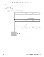
2.2.2 Measuring Total Wire Length
The total wire length of all combined branches of one SLC cannot exceed the limits set forth in each system’s instruction manual. Deter-
mine the total length in each SLC by summing all wire segments. In Figure 2.1 above, the picture on the right shows an SLC with 3
branches. Figure 2.2 below shows the same SLC divided into segments. The total length of the SLC is determined by adding the lengths
of Segment 1 + Segment 2 + Segment 3 + Segment 4 + Segment 5. No segment should be summed twice.
2.3 Four-Wire SLC Style 6 & 7 (Class A)
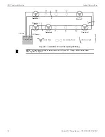
2.3.1 Measuring Loop Resistance
The total DC resistance of the SLC pair exceed:
•
50 ohms for NFS-320, NFS2-640, NFS-640, LCM-320, LEM-320, LIB-200A and LIB-400
•
40 ohms for AFP-100, AFP-200, AFP-300/400, LIB-200, AIM-200.
Measure DC resistance as detailed and shown below:
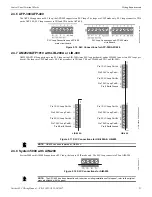
1.
Disconnect the SLC channel B (Out) and SLC channel A (Return) at the control panel.
2.
Short the SLC at the last device and measure the resistance at SLC Out. Record resistance and remove the short. Refer to Figure 2.3.
3.
Short the SLC at the first device and measure the resistance at SLC return. Record resistance and remove the short. Refer to
The maximum DC resistance of the SLC is the higher of 2 and 3.
SL
C-m
ea
s5.wmf
SLC Out
Branch
Short Point
SLC Terminal
Block
B+ B–
Branch A
Branch B
Branch C
Figure 2.1 Measuring DC Resistance of a Two-Wire SLC
Branch A
Branch C
S
LC
-mA
ea
s2
.wm
f
SLC Terminal Block
Segment
Two
Segment
Five
Segment
Three
Segment
Four
Segment
One
Figure 2.2 Measuring the Total Wire Length of a Two-wire SLC
Branch B