L7124U UNIVERSAL OIL ELECTRONIC AQUASTAT® CONTROLLER
3
69-1232—2
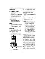
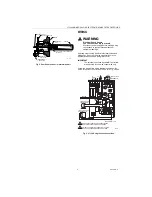
Fig. 2. Position of sensor in immersion well.
WIRING
WARNING
Electrical Shock Hazard.
Can cause serious injury or death.
Disconnect power supply before making wiring
connections to prevent electrical shock or
equipment damage.
All wiring must comply with local electrical codes and
ordinances. Do not exceed the specifications in the
Application section when wiring this control.
IMPORTANT
The terminals on these Aquastat® Controllers
are approved for use with copper wire only.
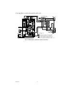
Follow the appropriate wiring diagrams shown on the
inside of the front cover of the L7124U or in Fig. 3 and 4.
Fig. 3. L7124U single zone connections.
SENSOR WIRES
IMMERSION WELL
CLAMP SCREW
IMMERSION
WELL CLAMP
M16120
HEAT-CONDUCTIVE COMPOUND
(OPTIONAL)
CONTROLLER CASE
BOILER
IMMERSION
WELL
SENSOR
LOW
LIMIT
HIGH
LIMIT
DIFF.
SENSOR
PWR
T
L2
T
TSTAT
DSBL
LL
B
B2
B1
C2
ZR
ZC
C1
C
ZC
1
2
M17776
L1
(HOT)
L2
1
1
2
2
POWER SUPPLY. PROVIDE DISCONNECT MEANS
AND OVERLOAD PROTECTION AS REQUIRED.
CONTROL CASE MUST BE CONNECTED TO EARTH
GROUND. USE GROUNDING SCREW PROVIDED.
LINE VOLTAGE OIL
BURNER RELAY
LINE VOLTAGE
CIRCULATOR
LOW VOLTAGE
THERMOSTAT
T1
LEGEND: = LED
SENSOR
L1
F01
Содержание L7124U
Страница 7: ...7 69 1232 2 ...


