

Circuit Diagram
Frequency Response
Polar Diagram
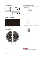
Installation Instructions
1. Disassemble the U-shaped bracket from the cabinet and
screw it on the wall.
2. Select power radiation based on input signal by power
tapping switch.
3. Connect the input with the positive and negative terminals
properly.
10W
20W
40W
Com
2
M_L-PWP40A_EN_2.1
20Hz
50
100
200
500
1k
2k
5k
10k
20k
30
40
50
60
70
80
90
dB/SPL
20
© 2012 Honeywell International Inc. All rights reserved.
-6dB
0
-12dB
-18dB
-24dB
-30dB
-30dB
-24dB
-18dB
-12dB
-6dB
0
30
°
60
°
90
°
120
°
150
°
180
°
0
°
30
°
60
°
90
°
120
°
150
°
180
°
0
°


