45
Installation Notes
Note 1. Warning!
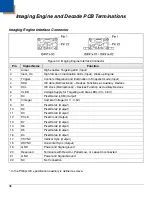
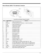
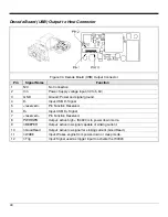
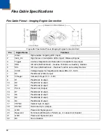
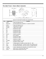
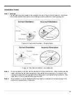
The flex cable must be installed in the orientation shown in Figure 39 and Figure 40. If the cable
is incorrectly installed, the engine can be damaged, and the warranty voided, see page 49.
Figure 39. Flex Cable Orientation – Imaging Engine
Figure 40. Flex Cable Orientation – Decode Board
Note 2.
Proper installation of the flex cable is essential for engine performance. When installing the flex
cable, verify that the flex cable receptacle is fully seated in the engine plug. To achieve a full
connection, ensure that the alignment of the mating parts is not angled during installation. Flex
cable P/N 77-77104 is designed with universal ends.
Note 3.
Once installed, it is recommended that the flex cable be connected and routed securely in the
enclosure to prevent loss of connection.
Содержание IS4920
Страница 1: ...IS4920 IS4921 Area Imaging Decode Engine Integration Guide ...
Страница 6: ......
Страница 8: ...2 Models and Accessories Figure 1 Part Number Designations ...
Страница 15: ...9 Figure 10 IS4910 02 IS4911 02 Dimensions ...
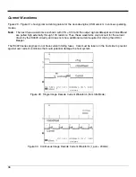
Страница 43: ...37 Figure 31 Power Up Boot Up Current Waveform ...
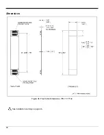
Страница 50: ...44 Dimensions Figure 38 Flex Cable Dimensions P N 77 77104 See installation warning on page 45 ...
Страница 61: ...Honeywell Scanning and Mobility 90 Coles Road Blackwood NJ 08012 4683 00 05325 Rev F March 2009 ...


