Configuration
Rev 3.01
38
Document 900.0258
10/05
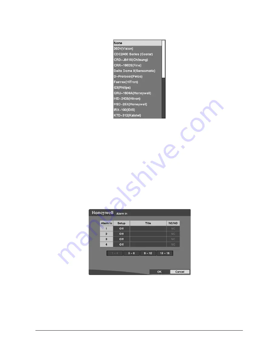
Figure 3-18
PTZ Device List
4.
To assign IDs to each camera, highlight the ID heading and then press
#
. To
change the number, highlight it and use the Up and Down Arrow buttons to
increase and decrease the numbers. The PTZ ID number can be set from 0 to 256.
Alarm In Setup Screen
The alarm terminal strip on the back of the DVR has inputs associated with each alarm.
The inputs are displayed in groups of four. Use the Alarm In Setup screen to configure
each alarm input. Highlight Alarm In in the Device menu (MENU
➤
Device
➤
Alarm-In) and then press
#
. The Alarm In setup screen displays.
Figure 3-19
Alarm In Screen
The alarm terminal strip on the back of the DVR has inputs associated with each alarm.
The inputs are displayed in groups of four. You can turn each input On or Off. Each
input can be given a title, and the inputs can be set as NO (normally open) or NC
(normally closed) independently.
To change the settings for all the cameras on the page (for example, cameras 1 to 4 in
Figure 3-19
), select either the Setup heading or the NC/NO heading first, then change
the option.
Содержание HRHD16+
Страница 6: ......
Страница 10: ...Contents Rev 3 01 iv Document 900 0258 10 05 ...
Страница 14: ...Figures Rev 3 01 viii Document 900 0258 10 05 ...
Страница 16: ...Tables Rev 3 01 x Document 900 0258 10 05 ...
Страница 24: ...Introduction Rev 3 01 4 Document 900 0258 10 05 ...
Страница 114: ...Operation Rev 3 01 94 Document 900 0258 10 05 ...
Страница 118: ...Solutions Rev 3 01 98 Document 900 0258 10 05 ...
Страница 120: ...Connector Pinouts Rev 3 01 100 Document 900 0258 10 05 RS485 Connector Pinouts RX TX Master unit Slave unit ...
Страница 121: ...Map of Screens Rev 3 01 101 Document 900 0258 10 05 D Map of Screens Figure D 1 Screen Map ...
Страница 122: ...Map of Screens Rev 3 01 102 Document 900 0258 10 05 ...
Страница 130: ...Rev 3 01 6 Document 900 0258 10 05 ...
Страница 131: ......


