!
5.
Maintenance
With the description of the individual maintenance steps, the same position numbers are used here for the
identification of the component as can be found in the spare parts drawing (page 12) and the spare parts list
(page 13 and 14).
For simple, easy maintenance work, we recommend following the sequence of the individual steps.
The device must be dismantled from the plant prior to maintenance work.
5.1
Dismantling the proximity sensors
Prior to the dismantling of the drive unit of the mixer and the maintenance work, we strongly
recommend removing the proximity sensors (117) from the device in order to prevent damage.
Prior to their removal, the proximity sensors should be disconnected from the power source.
Unscrew the cable sockets (118) from the proximity sensors.
Loosen the counter nuts and unscrew the proximity sensors from the receptacle (115).
5.2
Dismantling the drive unit
Remove the cap (121), unscrew the hexagon nut (120) and remove the washer (119) from the threaded rod (111).
Unscrew both cylinder screws (116) located behind the conical washer (119) and remove the receptacle (115).
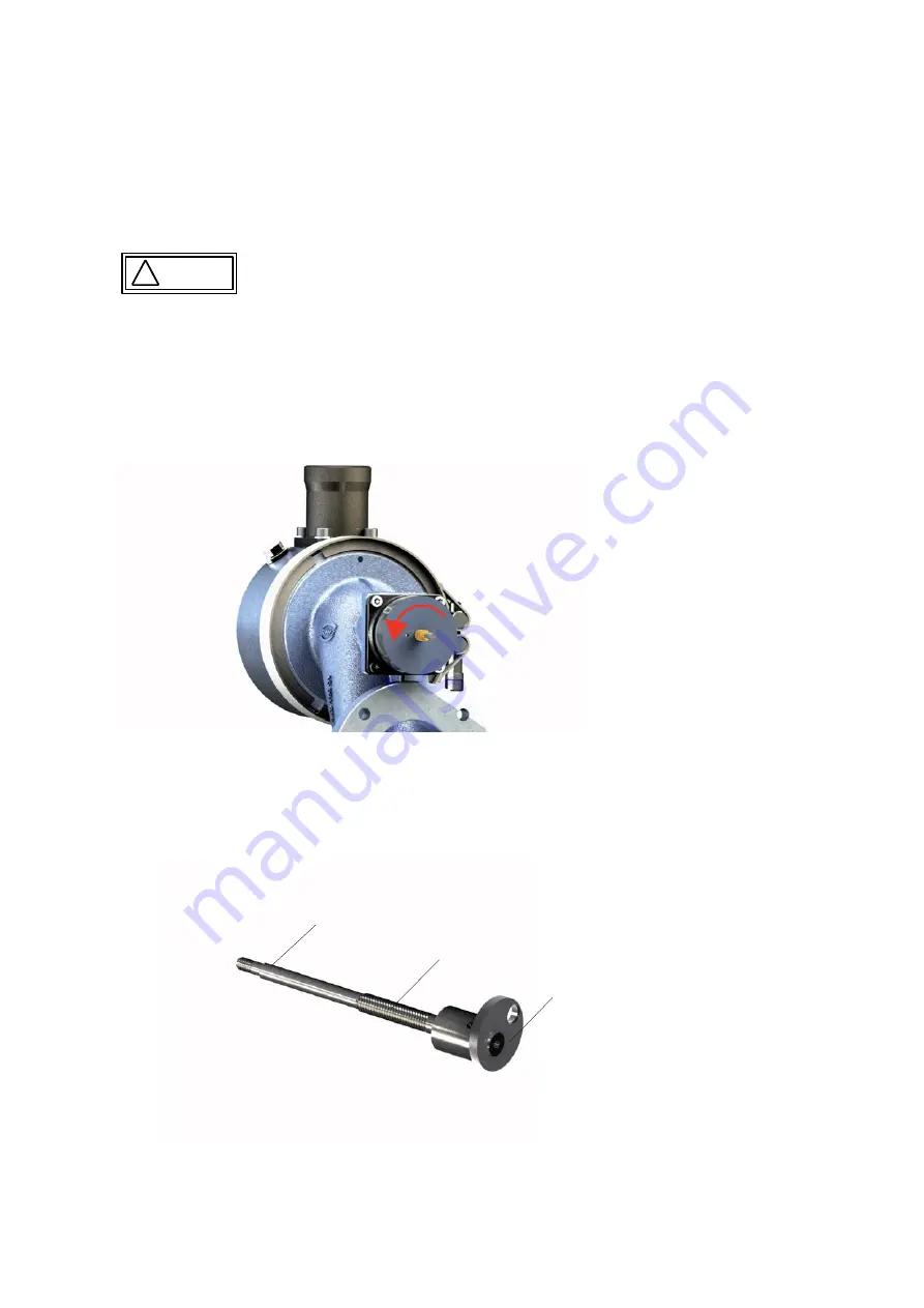
By turning the motor spindle (Figure 7), the venturi insert (101) is first pushed to the mechanical stop on the
mixer body (130) and then unscrewed from the threaded rod with additional rotation of spindle of the stepper
motor (113).
Caution
The next step is the removal of the threaded rod (111) from the device. For this purpose, unscrew the inspection
glass (109) from the induction elbow (133) and loosen the clamp connection between the threaded rod and the
pin (105) by loosening the threaded pin (110).
The threaded rod is an assembly including the following individual parts: Rod thread M6, rod thread M4 and fixing
washer (see Figure 8 and Table 6) are adhered together. Check that all adhesive connections are firmly seated.
Fig 7:
Rotation direction of the motor spindle with removal of the drive unit
Rod thread M4
Rod thread M6
Fixing washer
Fig 8:
Threaded rod assembly (111)
Then carefully clean and dry all dismantled parts. Check the condition of the transmission thread (motor spindle interior
and threaded rod exterior (111)).
Lightly spray the transmission thread (M6) on the threaded rod and the contact surfaces on the outer diameter of the
washer (119) with slip agent (Table 5). The recommended coating thickness is 5 – 15 μm. Shake slip agent spray can
well before use. We recommend coating the threaded surfaces in a crossing pattern. Allow sprayed surfaces to dry for
5 – 7 minutes at room temperature.
985.29-2 p.09


