background image


HON


670 / HON


671 

Controllers 

Component documentation, 
Maintenance manual and spare parts 

Содержание HON 670

Страница 1: ...HON 670 HON 671 Controllers Component documentation Maintenance manual and spare parts ...

Страница 2: ...sure unit 35 4 7 Mounting the pressure unit on the controller 38 4 8 Completing the maintenance 38 5 Storage and disposal 39 5 1 Storing the device 39 5 2 Disposing of the device 40 6 Appendix 41 6 1 Re engage differential 41 6 2 Additional information regarding spare parts 42 6 3 K16 K17 K18 K19 Spare parts drawing for baseplate and connections 44 6 4 K16 Spare parts drawing for diaphragm measuri...

Страница 3: ...nctions in a number of different sizes For this reason we are unable to guarantee that the illustrations in this documentation will match the dimensions of your product In these cases the illustrations should be viewed as a concept sketch Failing to observe the information provided in this document may lead to injuries including death and material damages To ensure the safety any persons handling ...

Страница 4: ... ks honeywell com Website www honeywellprocess com www hongastec de Printed in Germany The manufacturer will not be liable for damages and malfunctions arising from failure to observe this component documentation and other applicable documents The written approval from Honeywell Gas Technologies GmbH Kassel is required for any modifications and additions to the product Any violation will void the ...

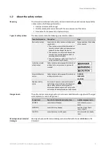
Страница 5: ...f the chapter Instruction related safety notices Safety notices containing specific instructions relating to the entire manual or a group of manuals Step related safety notices Safety notices containing specific instructions relating only to the step DANGER WARNING CAUTION Additional safety notice Instruction to observe certain safety notices with reference to a location in the document where safe...

Страница 6: ...t be coordinated in consultation with the manufacturer The controllers HON670 HON671 which conform to DIN EN 334 DIN EN 14382 are in tended to be used for the following gas pressure regulators HON 372 HON 402 HON 408 HON 503 HON 512 HON 530 HON 703 HON 704 HON 711 HON 721 HON 5020 Please observe the following limitations of use Do not use the device for any media other than those mentioned in the ...

Страница 7: ...lower response pres sure Control range Wdsu Thread type bar psi K17 Diaphragm measuring unit 2 0 20 29 290 HON 671 K17 Diaphragm assembly with ball guide sleeve 10 40 145 580 Metric K19 Metal bellows measuring unit 20 90 290 1305 The designs that use the imperial system of measurement feature ports that conform to Anglo American thread standards and use inches as a unit The designs that use the me...

Страница 8: ...bels Make sure you have the right component documentation for your device To identify your device look at the nameplate Make sure that the conditions on site correlate with the information on the type plate and the technical specifications Technical specifications The monitoring device type plate locations are as follows Figure No Description 1 Type plate on the side of the monitoring device 2 Add...

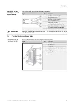
Страница 9: ... see configuration pdsu Lower response pressure value Small color coded text labels must be used to mark the controller s connection lines based on what the lines are used for 2 4 Physical design and operation The controller is made up of the following individual components Figure No Description 1 Spring adjuster 2 Pilot spring 3 Comparator stage with diaphragm meas uring unit 4 Amplifying valve 5...

Страница 10: ...age with diaphragm meas uring unit with ball guide sleeve 5 Amplifying valve 6 Base plate The controller is made up of the following individual components Figure No Description 1 Spring adjuster 2 Pilot spring 3 Ball guide sleeve 4 Amplifying valve 5 Comparator stage with metal bellows measuring unit 6 Base plate Physical design of the controllers K16 K17 with ball guide sleeve Physical design of ...

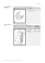
Страница 11: ...al components Figure No Description 1 Piston 2 Controller connection The controller features the following connections Figure No Connection Pipe connection thread type Metric Imperial 1 Measuring line E12L 1 2 2 Vent line E12L 1 2 3 Pressure unit E10L 3 8 Physical design of the pressure unit Controller connection lines ...

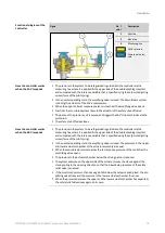
Страница 12: ...r via the measuring line where it is applied to the upper side of the double diaphragm system and compared with the reference variable that is specified using the setpoint adjusting screw force of the pilot spring In the normal operating state the amplifying valve is closed The pressures in the upper and lower actuator chamber of the actuator assembly are equal When the monitored pressure reaches ...

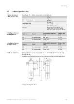
Страница 13: ...rpressure bar Response time sec K16 Via manual actuator 0 8 40 00 0 1 0 3 K18 Via manual actuator 20 00 90 0 0 1 0 3 Controller Manual Automatic for underpressure bar Response time sec K17 Via manual actuator 2 0 40 00 0 1 0 3 K19 Via manual actuator 20 00 90 0 0 1 0 3 The figure below shows the dimensions for the controller K16 K17 for the control range Wd 0 8 40 bar Comparator stage Diaphragm me...

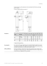
Страница 14: ... 195 340 60 60 75 85 50 60 38 38 Stage with ball guide sleeve The properties of the gas conveyed through the controllers HON 670 HON 671 must meet the requirements specified by the DVGW German Technical and Scientific Association for Gas and Water in the latest version of DVGW Code of Practice G 260 A The device s mechanical components do not contain any potential sources of ignition and according...

Страница 15: ... its use in hazardous locations All work with and on the device must be carried out only after the presence of an explosive atmosphere has been fully ruled out Only use the device for the intended purpose Never use the device for any other po tentially logical purposes Follow all the safety measures outlined in this component documentation and on the device In particular wear the mandatory persona...

Страница 16: ...ce operating pressure equipment and systems Knowledge of the relevant standards and regulations Ability to identify and avoid dangers autonomously Any persons handling the device must be equipped with the following personal protective gear Task Required personal protective gear Mechanical activities involved in mainte nance storage disposal Safety boots with protection for electrostatic dis charge...

Страница 17: ...roceed as follows Step Description Explanation 1 Have the maintenance and servicing parts ready Refer to the topic Explanation of spare parts to find out which spare parts drawings belong to your device model and have the corresponding maintenance and service parts ready before starting maintenance The spare parts that are always required for the controller s maintenance are listed in the spare pa...

Страница 18: ...ntroller please refer to the user manual for the relevant gas pressure regulator Keep in mind that it is always necessary to depressurize the actuator assembly including the controller and purge all gas conveying lines with nitrogen before removal The maintenance described below uses the controller with a diaphragm measuring unit and the controller with a metal bellows measuring unit as an example...

Страница 19: ...nit Crush and impact hazard posed by components falling or toppling over accidentally When working with heavy components that have been removed or are yet to be installed injury may result if the components start moving in an uncontrolled manner e g fall down from the working surface or topple over Place removed components exclusively on level horizontal working surfaces with enough load bearing c...

Страница 20: ...double dia phragm system Hex nut 20 Nm 15 ft lbs 6 Assembling the double dia phragm system Baseplate screws 12 Nm 9 ft lbs 7 Mounting the controller Screws of bottom cover 12 Nm 9 ft lbs 8 Mounting the controller Proceed as follows Figure Step Description 1 Unscrew the 4 screws 1 on the baseplate 2 Remove the baseplate 1 3 Replace the 4 O rings 1 with 4 new lubricated O rings Bear in mind that the...

Страница 21: ...if the pilot spring is not completely relaxed 3 Replace the O ring 1 with a new lubri cated O ring Lubricate the thread surfaces Note See the appendix for the lubricants to be used 4 Put the cover 2 in place Tighten the 4 screws 1 of the cover using a crosswise pattern Tightening torque 12 Nm 9 ft lbs 5 Screw the hex flange nut 2 back in a bit and screw in the spring adjuster 1 by a few turns The ...

Страница 22: ...r and remove the lower cover 2 2 Remove the double diaphragm system 1 by lifting it off 3 Counter the diaphragm plate 2 and unscrew the hex nut 1 4 Remove the following parts Diaphragm plate 1 Diaphragm 2 5 Turn the double diaphragm system over Counter the diaphragm plate 2 and unscrew the cap nut 1 Dismantling and remov ing the double diaphragm system ...

Страница 23: ...ith a new lubricated O ring Note See the appendix for the lubricants to be used 2 Take out the piston 1 3 Remove the following parts Diaphragm plate 1 Diaphragm 2 4 Screw the assembly aid 1 into the internal thread of the nozzle 2 5 Hold the connecting piece in place 1 and pull the nozzle 2 out Replacing the wear parts of the double diaphragm system ...

Страница 24: ...kets 2 into the new diaphragms Proceed as follows Figure Step Description 1 Turn the nozzle 1 such that the pin 2 is positioned coaxially to the bore 2 Keep the connecting piece 1 in position and insert the nozzle 2 into the connect ing piece 1 until it can go no further 3 Put the new diaphragm 2 and the dia phragm plate 1 in place Make sure that the diaphragm is aligned correctly The side of the ...

Страница 25: ... 20 Nm 15 ft lbs When doing so the castellated nut of the new piston will close 6 Turn the double diaphragm system over Put the new diaphragm 3 and the dia phragm plate 2 in place Counter the diaphragm plate and tighten the hex nut firmly 1 Tightening torque 20 Nm 15 ft lbs 7 Make sure that the diaphragm is aligned correctly The side of the diaphragm that has a depression at the center should be f...

Страница 26: ...o the left Mark this position 3 Turn the diaphragm plate to the central position between the two marks The diaphragm plate is now aligned correctly 4 Put the double diaphragm system into place 5 Put the bottom cover 2 in place Tighten the 4 screws 1 only finger tight 6 Mount the baseplate 1 Tighten the 4 screws 2 only finger tight ...

Страница 27: ...ific controller version proceed as indicated in the relevant section Maintenance on the pressure unit see page 35 4 5 Maintenance on the controller with metal bellows measuring unit Crush and impact hazard posed by components falling or toppling over accidentally When working with heavy components that have been removed or are yet to be installed injury may result if the components start moving in...

Страница 28: ...of pilot spring cover 12 Nm 9 ft lbs 4 Replace the O ring of the pilot spring cover Cap nut 15 Nm 11 ft lbs 5 Assembling the diaphragm system Metal bellows screw 15 Nm 11 ft lbs 6 Assembling the diaphragm system Screws of bottom cover 12 Nm 9 ft lbs 7 Assembling the controller Baseplate screws 8 Nm 6 ft lbs 7 Assembling the controller Proceed as follows Figure Step Description 1 Unscrew the 4 scre...

Страница 29: ...if the pilot spring is not completely relaxed 3 Replace the O ring 1 with a new lubri cated O ring Lubricate the thread surfaces Note See the appendix for the lubricants to be used 4 Put the cover 2 in place Tighten the 4 screws 1 of the cover using a crosswise pattern Tightening torque 12 Nm 9 ft lbs 5 Screw the hex flange nut 2 back in a bit and screw in the spring adjuster 1 by a few turns The ...

Страница 30: ...rew the 4 screws 1 of the lower cover and lift the cover off 2 2 Lift off the metal bellows 1 with the base plate 2 3 Unscrew the metal bellows 1 from the base plate 2 4 Replace the 2 O rings 1 with 2 new lubricated O rings Note See the appendix for the lubricants to be used Replacing the O rings of the metal bellows ...

Страница 31: ...phragm system over Counter the diaphragm plate 2 and unscrew the cap nut 1 2 Take out the piston 1 3 Remove the following parts Diaphragm plate 1 Diaphragm 2 4 Screw the assembly aid 1 into the internal thread of the nozzle 2 5 Hold the connecting piece in place 1 and pull the nozzle 2 out Disassembling the dia phragm system ...

Страница 32: ...ee the appendix for the lubricants to be used 2 Replace the diaphragm 1 Place a new snap on gasket 2 into the new diaphragm 3 Replace the O ring 1 of the cap nut with a new lubricated O ring Note See the appendix for the lubricants to be used Proceed as follows Figure Step Description 1 Turn the nozzle 1 such that the pin 3 is positioned coaxially to the bore Replacing the wear parts of the diaphr...

Страница 33: ...ression at the center should be facing upward 4 Insert the new piston 2 Risk of confusion Please observe the characterizing difference between the old and the new piston Old piston 1 Castellated nut closed New piston 2 Castellated nut open 5 Put the cap nut 1 in place Counter the diaphragm plate 2 and tighten the cap nut firmly Tightening torque 15 Nm 11 ft lbs When doing so the castellated nut of...

Страница 34: ...the right Mark this position 2 Turn the diaphragm plate all the way to the left Mark this position 3 Turn the diaphragm plate to the central position between the two marks The diaphragm plate is now aligned correctly 4 Put the metal bellows 1 with the base plate 2 in place 5 Put the lower cover 2 in place Tighten the 4 screws 1 of the lower cover only finger tight Assembling the controller ...

Страница 35: ...nance on the pressure unit see page 35 4 6 Maintenance on the pressure unit Crush and impact hazard posed by components falling or toppling over accidentally When working with heavy components that have been removed or are yet to be installed injury may result if the components start moving in an uncontrolled manner e g fall down from the working surface or topple over Place removed components exc...

Страница 36: ...n this section Part Tightening torque Step Cover screws 8 Nm 6 ft lbs 8 Proceed as follows Figure Step Description 1 Unscrew and remove the 6 screws 1 of the cover 2 Remove the cover 3 Replace the O ring with a new lubricated O ring Note See the appendix for the lubricants to be used 4 Take out the piston Maintenance on the pressure unit ...

Страница 37: ...ep Description 5 Replace the piston seal 1 with a new lubricated piston seal 6 Insert the piston 7 Put the cover in place 8 Tighten the 6 screws 1 using a crosswise pattern Tightening torque 8 Nm 6 ft lbs Proceed as follows Mounting the pressure unit on the controller Next task ...

Страница 38: ...ign particles swarf and soiling If screws bolts or washers are replaced with identical new parts any oil on these new parts must first be removed Proceed as follows Figure Step Description 1 Mount the pipe joint on the screw con nections 1 and 2 Proceed as follows Completing the maintenance see page 38 4 8 Completing the maintenance For instructions on how to install the controller on the actuator...

Страница 39: ...owing rules apply to the storage of spare parts Apply an appropriate protective agent to assemblies at risk of corrosion If stored correctly O rings and gaskets should not be kept longer than 7 years Store the spare parts in the original package until they are used Observe the following rules All device openings and fittings must be sealed and protected from soiling and damage The device s mainten...

Страница 40: ... to the appropriate disposal not all of the items may be applicable to your device Dispose of the metals according to their types and grades steel scrap cast iron scrap light alloy scrap nonferrous heavy metal scrap synthetic rubber scrap electronic scrap Recycle elements made of synthetic materials Dispose of any other components according to the quality of the materials Appropriate disposal ...

Страница 41: ...ng parts for the controllers 60 Lubricants threadlockers and special tools 65 6 1 Re engage differential Pilot spring Overpressure Underpressure Spring no Wire diameter mm Color marking Specific control range W dso bar Re engage differential p wo be tween p dso and normal operating pressure bar Specific control range W dsu bar Re engage differential p wu be tween normal operating pressure and p ds...

Страница 42: ... allowed to be ordered or replaced without first contacting the manufacturer The spare parts always required for maintenance of the controller are grouped together into spare parts kits appropriate for the device in question Each spare parts kit has its own part number part no Individual maintenance and servicing parts can be ordered using the corresponding part number which is specified in the bi...

Страница 43: ...kits for SBV response NBR and FKM variants K17 Spare parts drawing for diaphragm measuring unit Spare parts kits for SAV response NBR FKM and NBR low temperature vari ants K17 Spare parts drawing for diaphragm measuring unit with guide sleeve Spare parts kits for SAV response NBR FKM and NBR low temperature vari ants K18 Spare parts drawing for metal bellows measuring unit Spare parts kits for SAV...

Страница 44: ...Appendix HON 670 HON 671 Controllers Component Documentation 44 6 3 K16 K17 K18 K19 Spare parts drawing for baseplate and connections K16 K17 K18 K19 ...

Страница 45: ...ising performance curve K16 diaphragm measuring unit for SAV response NBR variant Name Description Part no Spare parts kit K16 diaphragm measuring unit for SAV response NBR variant Consisting of 3 each of no 12 1 each of no 19 1 each of no 106 2 each of no 107 1 each of no 108 1 each of no 113 2 each of no 119 1 each of no 122 1 each of no 1004 1 each of no 1005 K670 001 Spare parts kits ...

Страница 46: ...erature variant Name Description Part no Spare parts kit K16 diaphragm measuring unit for SAV response NBR low temperature variant Consisting of 3 each of no 12 1 each of no 19 1 each of no 106 2 each of no 107 1 each of no 108 1 each of no 113 2 each of no 119 1 each of no 122 1 each of no 1004 1 each of no 1005 K670 005 K16 diaphragm measuring unit for SBV response NBR variant Name Description P...

Страница 47: ...ts kit K16 diaphragm measuring unit for SBV response FKM variant Consisting of 3 each of no 12 1 each of no 19 1 each of no 106 2 each of no 107 1 each of no 108 1 each of no 113 2 each of no 119 1 each of no 122 1 each of no 1004 1 each of no 1005 K670 004 Optionally nos 107 207 407 507 sprayed with Teflon Mat No 10002796 diaphragm beaded 33 28 0 52 PTFE ...

Страница 48: ...trollers Component Documentation 48 6 5 K16 Spare parts drawing for diaphragm measuring unit with ball guide sleeve Controller 16 diaphragm measuring unit with ball guide sleeve Wdo 10 bar to 40 bar Stage rising performance curve ...

Страница 49: ...cription Part no Spare parts kit K16 diaphragm measuring unit with ball guide sleeve for SAV response FKM variant Consisting of 3 each of no 12 1 each of no 19 1 each of no 206 2 each of no 207 1 each of no 208 1 each of no 213 2 each of no 219 1 each of no 222 1 each of no 1004 1 each of no 1005 K670 002 K16 diaphragm measuring unit with ball guide sleeve for SAV response NBR low temperature vari...

Страница 50: ...213 2 each of no 219 1 each of no 222 1 each of no 1004 1 each of no 1005 K670 003 K16 diaphragm measuring unit with ball guide sleeve for SBV response FKM variant Name Description Part no Spare parts kit K16 diaphragm measuring unit with ball guide sleeve for SBV response FKM variant Consisting of 3 each of no 12 1 each of no 19 1 each of no 206 2 each of no 207 1 each of no 208 1 each of no 213 ...

Страница 51: ...alling performance curve K17 diaphragm measuring unit for SAV response NBR variant Name Description Part no Spare parts kit K17 diaphragm measuring unit for SAV response NBR variant Consisting of 3 each of no 12 1 each of no 19 1 each of no 406 2 each of no 407 1 each of no 408 1 each of no 413 2 each of no 419 1 each of no 422 1 each of no 1004 1 each of no 1005 K670 001 Spare parts kits ...

Страница 52: ... 419 1 each of no 422 1 each of no 1004 1 each of no 1005 K670 002 K17 diaphragm measuring unit for SAV response NBR low temperature variant Name Description Part no Spare parts kit K17 diaphragm measuring unit for SAV response NBR low temperature variant Consisting of 3 each of no 12 1 each of no 19 1 each of no 406 2 each of no 407 1 each of no 408 1 each of no 413 2 each of no 419 1 each of no ...

Страница 53: ...HON 671 Controllers Component Documentation 53 6 7 K17 Spare parts drawing for diaphragm measuring unit with ball guide sleeve Controller 17 diaphragm measuring unit Wdu 10 bar to 40 bar Stage falling performance curve ...

Страница 54: ...suring unit with ball guide sleeve for SAV response FKM variant Consisting of 3 each of no 12 1 each of no 19 1 each of no 506 2 each of no 507 1 each of no 508 1 each of no 513 2 each of no 519 1 each of no 522 1 each of no 1004 1 each of no 1005 K670 002 K17 diaphragm measuring unit with ball guide sleeve for SAV response NBR low temperature variant Name Description Part no Spare parts kit K17 d...

Страница 55: ...HON 670 HON 671 Controllers Component Documentation 55 6 8 K18 Spare parts drawing for metal bellows measuring unit Controller 18 metal bellows measuring unit Wdo 20 bar to 90 bar Stage rising performance curve ...

Страница 56: ...Part no Spare parts kit K18 metal bellows measuring unit FKM variant Consisting of 3 each of no 12 1 each of no 19 1 each of no 306 1 each of no 307 1 each of no 308 1 each of no 313 1 each of no 319 1 each of no 322 1 each of no 327 1 each of no 328 1 each of no 1004 1 each of no 1005 K670 007 K18 metal bellows measuring unit for SAV response NBR low temperature variant Name Description Part no S...

Страница 57: ...9 1 each of no 322 1 each of no 327 1 each of no 328 1 each of no 1004 1 each of no 1005 K670 003 K18 metal bellows measuring unit for SBV response FKM variant Name Description Part no Spare parts kit K18 metal bellows measuring unit for SBV response FKM variant Consisting of 3 each of no 12 1 each of no 19 1 each of no 306 1 each of no 307 1 each of no 308 1 each of no 313 1 each of no 319 1 each...

Страница 58: ...HON 670 HON 671 Controllers Component Documentation 58 6 9 K19 Spare parts drawing for metal bellows measuring unit Controller 19 metal bellows measuring unit Wdu 20 bar to 90 bar Stage falling performance curve ...

Страница 59: ...ing unit for SAV response FKM variant Consisting of 3 each of no 12 1 each of no 19 1 each of no 606 1 each of no 607 1 each of no 608 1 each of no 613 1 each of no 619 1 each of no 622 1 each of no 627 1 each of no 628 1 each of no 1004 1 each of no 1005 K670 007 K19 metal bellows measuring unit for SAV response NBR low temperature variant Name Description Part no Spare parts kit K19 metal bellow...

Страница 60: ...pressure unit Pressure unit 6 11 Maintenance and servicing parts for the controllers Maintenance parts for baseplate K16 K17 K18 K19 NBR FKM NBR low temperature variant No Letter No Letter No Letter No Letter Name Part no Part no Part no 12 12 12 12 O ring 20225 RMK 3 units 20633 RMK 3 units 100444 RMK 3 units ...

Страница 61: ...s 10000066 2 units 122 422 Piston pre assembled 10009662 10009662 10009662 Optionally nos 107 407 sprayed with Teflon Mat No 10002796 diaphragm beaded Maintenance parts for diaphragm measuring unit K16 SBV response No Letter Name NBR Part no FKM Part no 106 O ring 20225 RMK 20633 RMK 107 Diaphragm beaded 10000191 2 units 10000191 2 units 108 O ring 20332 RMK 20704 113 O ring 20293 RMK 20705 119 Sn...

Страница 62: ...etter Name NBR Part no FKM Part no 206 O ring 20225 RMK 20633 RMK 207 Diaphragm beaded 10000191 2 units 10000191 2 units 208 O ring 20332 RMK 20704 213 O ring 20293 RMK 20705 219 Snap on gasket 10000066 2 units 18357450 2 units 222 Piston pre assembled 10000186 10000186 Optionally no 207 sprayed with Teflon Mat No 10002796 diaphragm beaded Maintenance parts for metal bellows measuring unit K18 K19...

Страница 63: ... beaded 10000191 10000191 10000191 308 O ring 20332 RMK 20704 100992 RMK 313 O ring 20293 RMK 20705 100992 RMK 319 Snap on gasket 10000066 18357450 10000066 322 Piston pre assembled 10000186 10000186 10000186 327 O ring 20293 RMK 20705 100331 RMK 328 O ring 20416 20706 RMK 101299 Optionally no 307 sprayed with Teflon Mat No 10002796 diaphragm beaded Maintenance parts for pressure unit K16 K17 K18 ...

Страница 64: ...Spring plate suitable for control ranges Wdso 0 8 bar 1 5 bar 10000114 Wdso 1 bar 5 bar 10000114 Wdso 2 bar 10 bar 10000114 Wdso 5 bar 20 bar 10000114 409 Spring plate suitable for control ranges Wdsu 2 bar 10 bar 10000114 Wdsu 5 bar 20 bar 10000114 410 Compression spring optionally Wdsu 2 bar 10 bar 10000139 Wdsu 5 bar 20 bar 10000115 120 SAV valve insert 10009672 120 SBV valve insert 10000061 22...

Страница 65: ... All fittings Assembly paste 27 091 Important All parts must be coated slightly Use the following threadlockers Application Threadlocker Part no Closing cap threads Hex nut threads LOCTITE 26 688 You will need the following special tools for maintenance purposes Application Special tools Part no Topic Maintenance on the controller with dia phragm measuring unit see page 27 Maintenance on the contr...

Страница 66: ...arkway South Houston TX 77042 Phone 1 602 293 1866 Option 4 Honeywell Gas Technologies GmbH Osterholzstrasse 45 34123 Kassel Germany Phone 49 0 561 5007111 Emaar Business Park Building 2 Sheikh Zayed Road PO Box 232362 Dubai United Arab Emirates Phone 97144505800 Honeywell Engineering Sdn Bhd 1st Floor Block B No 10 Jalan Bersaru 13 4 46200 Petailing Jaya Selangor DE Malaysia Phone 603 7626 57000 ...

Отзывы: