background image

Rev 1.04

15

Document 900.0572

09/06

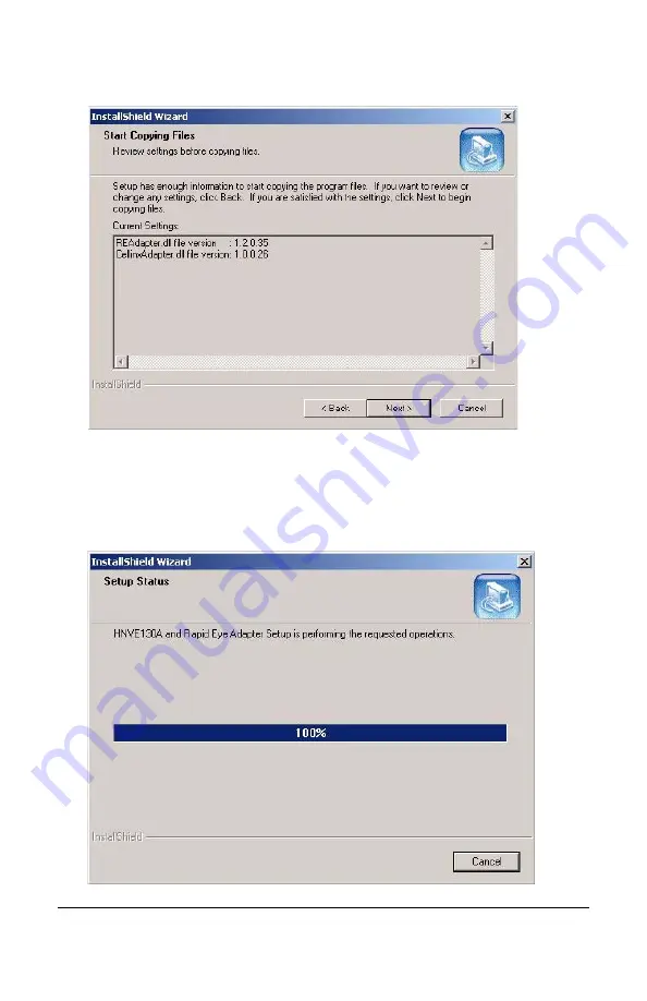
Figure 2-12

Start Copying Files

3.

Click Next to start copying the installation files. 

4.

If the Honeywell DVM client is open, a dialog box is displayed, prompting 
you to close the client. Close the client and click Yes to continue with the 
installation. 

Figure 2-13

 will appear.

Figure 2-13

Adapter Setup In Progress

Содержание HNVE130A

Страница 1: ...User Guide HNVE130A Document 900 0572 09 06 Rev 1 04 Video Streamer ...

Страница 2: ......

Страница 3: ...HNVE130A Video Streamer User Guide ...

Страница 4: ...isions Issue Date Revisions 1 00 09 05 New document 1 01 11 05 Correct Video Configuration Section 1 02 02 06 Added Install Adapter Patch section 1 03 07 06 Updated Adapter Patch and other sections 1 04 09 06 Replace Pelco D with Pelco Dome ...

Страница 5: ... party responsible for compliance could void the user s authority to operate the equipment This Class A digital apparatus complies with Canadian ICES 003 Cet appareil numérique de la Classe A est conforme à norme NMB 003 du Canada Œ This digital equipment fulfills the requirements for radiated emission according to limit B of EN55022 1998 and the requirements for immunity according to EN50130 4 19...

Страница 6: ...in board by anything other than a Lithium battery Dispose of used batteries according to the manufacturer s instructions This equipment and all communication wirings are intended for indoor use only To reduce the risk of fire or electric shock do not expose the unit to rain or moisture WEEE Waste Electrical and Electronic Equipment Electromagnetic Compatibility EMC The product must be installed an...

Страница 7: ...lling Adapter to DVM Client 14 Installing Adapter to DVM Server 16 Viewing Live Images 18 Configuring the Streamer 21 Network Wired 22 Video 22 Audio 23 Event 23 Date Time 23 OSD 24 Port 26 Security 26 Account 26 DDNS 27 Motion Detection 27 Firmware Update 27 PTZ Configuration 27 PTZ Control Method Using Streamer Settings 27 PTZ Control Method DVM Selects PTZ Protocol 30 3 Updating Firmware 33 App...

Страница 8: ...Rev 1 04 viii Document 900 0572 09 06 Appendix C Troubleshooting 41 Appendix D Specifications 43 ...

Страница 9: ...11 tblCamera Screen Scrolled to Password 13 Figure 2 12 Start Copying Files 15 Figure 2 13 Adapter Setup In Progress 15 Figure 2 14 InstallShield Wizard Complete 16 Figure 2 15 Start Copying Files 17 Figure 2 16 Stopping DVM Camera Service Services 17 Figure 2 17 InstallShield Wizard Complete 18 Figure 2 18 Internet Options 19 Figure 2 19 Security Settings 20 Figure 2 20 Web Browser Logon 21 Figur...

Страница 10: ...Rev 1 04 x Document 900 0572 09 06 ...

Страница 11: ...PTZ cameras with control capabilities The digital formats available include MJPEG MPEG1 MPEG2 MPEG4 and DivX Customizable performance of the encoder includes frame rate resolution and compression levels that can be dynamically configured to meet any system requirements Market Opportunities The HNVE130A is a cost effective way to leverage existing investments in analog video equipment while upgradi...

Страница 12: ...Z Camera Control Built in HTTP Web server for Configuration Supports Static IP and DHCP Technical Overview Hardware Inventory HNVE130A Network video encoder module DIO Connector Mounting L brackets and screws 2 Universal Input power supply Software utilities CD contains this User Guide Front and Rear Panels Figure 1 1 HNVE130A Front View Power LED Network LEDs DI DO PTZ RESET DIO RS485 AUDIO IN OU...

Страница 13: ...ereo plug accepts line level audio from a stereo audio source A pre amplifier is required when connecting a microphone to this input Audio Output A mini stereo plug produces stereo line level audio The output level is suitable for headphones but must be amplified to drive speakers Ethernet A standard RJ 45 cable is used to connect the Ethernet port to the local area network The Ethernet interface ...

Страница 14: ...lock and is used to control Pan Tilt Zoom PTZ cameras The PTZ protocol and serial port settings are configured via the web interface DO A single digital output is provided at the terminal block to control external devices The contacts are closed when active and are rated for 12V at 200 mA Future releases of the DVM system will be able to control this output DI A single digital input is provided at...

Страница 15: ...coder Installation Figure 1 3 Typical Encoder Installation DI DO PTZ RESET DIO RS485 AUDIO IN OUT OUT IN VIDEO 10 100BASE T DC 12V ETHERNET POWER Power Adapter Camera including PTZ Video In PTZ Control Ethernet Network Connection Monitor Video Out ...

Страница 16: ...Rev 1 04 6 Document 900 0572 09 06 ...

Страница 17: ...tional rack mount accessory If the encoder will be fastened to a surface the L brackets can be attached in one of three different locations as indicated in Figure 2 1 below Attach the L brackets to the encoder using the four 2 phillips screws provided Figure 2 1 Encoder Fastened to a Surface Back Mount for the Optional Rack Mount Accessory Front Mount for the Optional Rack Mount Accessory Surface ...

Страница 18: ...ately the L brackets can be mounted on either the front or back positions as indicated in Figure 2 2 Figure 2 2 Optional Rack Mount Accessory Sold Separately The optional rack mount accessory is attached to a 19 rack using the mounting hardware provided with the rack mount kit See Figure 2 2 for more details ...

Страница 19: ... 2 3 ENCP Application Interface Each encoder is factory configured with a default static IP address of 192 168 1 2 Configure the IP address as follows 1 Connect the encoder to the network with a CAT 5 cable and apply power 2 Click Scan Cameras on the ENCP application to obtain a list of encoders within the current network subnet The individual encoders can be identified from the list by reading th...

Страница 20: ...ds to re boot 9 Confirm that the IP address has updated correctly by viewing the MAC Address and IP Address on the right hand side of the application see Figure 2 3 Changing the Password Each encoder requires authentication with a user ID and password The administrator Admin account has an ID of root and is used by the DVM system to access and configure the encoder The default password for the adm...

Страница 21: ...llows a user to view images on the web interface without entering a user ID or password There is a hyperlink on the web interface login screen that provides guest access Guests are unable to change configuration The guest account can be activated by putting a check in the check box on the Account tab The guest account is active by default Changing the password in the DVM system will change the pas...

Страница 22: ...72 09 06 Changing the DVM Default Password 1 Open the DVM database tables see Figure 2 7 Figure 2 7 DVM System Tables 2 Right click tblStreamerTypes and select Open Table Return all rows Figure 2 8 Open Tables and Return All Rows ...

Страница 23: ... is the user ID for the administrator account on the HNVE130A Figure 2 9 tblStreamerTypes Screen Changing the HNVE130A Password 1 Open the DVM database tables 2 Right click tblCamera and select Open Table Return all rows 3 In the tblCamera screen change the StreamerPassword field for each of the streamers to match the password in each HNVE130A Figure 2 10 tblCamera Screen Figure 2 11 tblCamera Scr...

Страница 24: ...nstructions when installing the HNVE130A Adapter on the DVM R200 system as well as when you are upgrading the HNVE130A Adapter with any upgrades available from Honeywell in the future This installation needs to be done on all the DVM Clients as well as the Honeywell DVM Server if DVM is installed on two or more different machines If the DVM Server and Client are on the same machine run the install...

Страница 25: ...ick Next to start copying the installation files 4 If the Honeywell DVM client is open a dialog box is displayed prompting you to close the client Close the client and click Yes to continue with the installation Figure 2 13 will appear Figure 2 13 Adapter Setup In Progress ...

Страница 26: ...ld Wizard Complete 6 Click Finish to complete the Adapter installation Installing Adapter to DVM Server Following are the steps to install the Honeywell HNVE130A Adapter on the DVM Server 1 Double click the HNVE130A_RapidEye_Adapter exe executable file The welcome screen appears 2 Click Next The following screen will appear as shown in Figure 2 15 ...

Страница 27: ...Start Copying Files 3 Click Next to start copying the installation files The InstallShield Wizard stops the Honeywell DVM Camera Service and then continues with the installation Figure 2 16 will appear Figure 2 16 Stopping DVM Camera Service Services ...

Страница 28: ...erly before trying to view live images from the DVM system Live images can be viewed from an internet browser with the web interface An active X control must be downloaded to your computer before you will be able to view images The security settings on your browser may need to be modified to allow active X controls to be downloaded Configure and view live images as follows 1 Open Internet Explorer...

Страница 29: ...900 0572 09 06 Figure 2 18 Internet Options 4 Click the Custom Levels security button 5 Scroll down the list to the ActiveX controls and plug ins options and enable all active x control functions on the list see Figure 2 19 ...

Страница 30: ...og box 8 Enter the encoder s IP address in your browser s URL address box For example http 192 168 0 5 9 Select OK to download the active x controls for viewing video and follow the installation instructions 10 Re connect to the encoder if necessary by re entering the URL in the browser 11 Enter user ID and password in the login box to view images see Figure 2 20 ...

Страница 31: ...b interface Other settings such as network configuration and changing the password can be changed through the web interface but should be adjusted using the ENCP utility provided on the product CD along with this manual The web interface is accessed as follows 1 Open internet explorer or another internet browser of your choice 2 Connect to the HTTP server on the HNVE130A by entering its IP address...

Страница 32: ... the left pane of all pages and can be selected to proceed to each section They will be described in more detail below Network Wired Although the network configuration can be adjusted using the web interface it is better to use the ENCP application Adjusting the network configuration with the ENCP application will allow you to set the device address even if the address is not part of the current s...

Страница 33: ...tings may be configured on Figure 2 22 as follows Figure 2 22 Date TIme Screen Server Time This shows the time value which the HNVE130A keeps internally Time Zone User should select the proper time zone New Date Time User can manually assign the current date and time as desired Time Server User can use a Time Server to apply the current time to the unit After completing your changes click OK to sa...

Страница 34: ...ext information on the video Once enabled text is permanently overlayed onto the image see Figure 2 24 The DVM system is also capable of overlaying text information on the image but can be enabled or disabled during viewing it is not permanently overlayed onto the image Figure 2 23 OSD Screen ...

Страница 35: ...not currently supported Date Time or Channel Name Enable Check the box to display the items X Axis Input a point on the coordinate Y Axis Input a point on the coordinate Note The upper left corner of the image is X axis 0 Y axis 0 Set all coordinates within each setting s defined range see Figure 2 23 Figure 2 24 Live Video with OSD OSD Logo notcurrently supported Date time and channel name ...

Страница 36: ...m to contact the Encoder and should not be changed The default port number for video and audio is 1852 Security The security settings allow access to be restricted by client location within the network See Figure 2 25 Figure 2 25 Security Screen Account The account setting allows new user accounts to be created with different control access The DVM system will use the administrator ID root to acce...

Страница 37: ...tion There are two methods to control PTZ cameras In the first method the DVM System is configured to use streamer settings to control the PTZ The PTZ protocol is then selected by the HNVE130A In the second method the DVM system selects the PTZ protocol and the streamer passes the PTZ commands transparently to the PTZ camera PTZ Control Method Using Streamer Settings For this method the PTZ protoc...

Страница 38: ...rol outputs on the rear of the module are connected to the PTZ camera according to the instructions in the PTZ Installation Manual see Figure 1 1 for location of PTZ control outputs Refer to the following table or the Installation Guide for your PTZ camera to determine the correct baud rate number of stop bits and parity for the particular PTZ protocol you have selected Verify that the HNVE130A is...

Страница 39: ...re information Figure 2 27 PTZ Viewing Controls Configure the DVM system for PTZ operation as follows 1 Open Internet Explorer and browse to the DVM home page 2 Select the desired HNVE130A from the camera list on the left hand side Figure 2 28 DVM System Camera List 3 Select the Camera Control tab to open the control page see Figure 2 29 ...

Страница 40: ...ive view page 6 Test the PTZ controls to verify correct operation see Figure 2 30 Figure 2 30 DVM System PTZ Controls PTZ Control Method DVM Selects PTZ Protocol In this method the DVM system determines the camera protocol and the HNVE130A passes the commands transparently to the PTZ camera The HNVE130A is configured for PTZ operation through the HTTP interface as follows 1 Open internet explorer ...

Страница 41: ...0A has been configured for PTZ operation verify that the PTZ RS485 control outputs on the rear of the module are connected to the PTZ camera according to the instructions in the PTZ Installation Guide see Figure 1 1 for location of PTZ control outputs Also confirm that the PTZ camera protocols and baud rates are correctly set and match the protocol selected by the HNVE130A by referring to the PTZ ...

Страница 42: ...Rev 1 04 32 Document 900 0572 09 06 ...

Страница 43: ...your PC 2 Enter the encoder s IP address in your browser s URL address box 3 Enter the user ID and password and click the Server Settings hypertext link 4 Click Firmware Update on the left hand side list 5 Click Browse on the firmware update section on the right hand side of the application to select the new firmware file saved on your computer 6 Click Upload and enter the user ID and password to ...

Страница 44: ...Rev 1 04 34 Document 900 0572 09 06 ...

Страница 45: ...otion High Motion QCIF PAL 176x144 NTSC 176x112 Maximum 785 4 737 9 686 4 337 1 316 7 294 6 High 870 4 833 7 750 0 373 5 357 8 321 9 Medium 1009 1 985 6 862 0 433 1 423 0 369 9 Low 1252 6 1209 0 1034 2 537 6 518 8 443 8 Minimum 1573 7 1281 3 1285 0 675 4 549 9 551 5 CIF PAL 352x288 NTSC 352x240 Maximum 1491 3 1391 3 1158 5 640 0 597 1 497 2 High 1674 3 1560 3 1252 0 718 5 669 6 537 3 Medium 1974 3...

Страница 46: ...ion Low Motion High Motion QCIF PAL 176x144 NTSC 176x112 Maximum 97 2 121 3 139 9 41 7 52 1 60 0 High 110 2 141 1 162 9 47 3 60 6 69 9 Medium 126 9 169 0 195 6 54 5 72 5 83 9 Low 178 1 228 8 227 8 76 4 98 2 97 8 Minimum 315 8 337 0 450 9 135 5 144 6 193 5 CIF PAL 352x288 NTSC 352x240 Maximum 248 2 288 3 318 2 106 5 123 7 136 6 High 283 2 322 2 352 9 121 5 138 3 151 4 Medium 383 8 395 6 413 8 164 7...

Страница 47: ...ow Motion High Motion QCIF PAL 176x144 NTSC 176x112 Maximum 71 0 98 6 111 2 30 5 42 3 47 7 High 81 5 112 8 131 8 35 0 48 4 56 6 Medium 98 5 133 5 161 5 42 3 57 3 69 3 Low 134 5 185 8 231 3 57 7 79 7 99 3 Minimum 246 9 295 5 416 0 106 0 126 8 178 5 CIF PAL 352x288 NTSC 352x240 Maximum 187 2 223 5 273 0 80 3 95 9 117 2 High 214 1 262 1 307 2 91 9 112 5 131 8 Medium 310 4 317 1 372 7 133 2 136 1 159 ...

Страница 48: ... 7 423 6 445 2 534 6 Low 1455 8 1476 0 1745 8 624 8 633 4 749 2 Minimum 3053 2 3032 0 3870 8 1310 3 1301 2 1661 2 Table A 3 DivXMPEG4 IP GOP15 File Sizes Cont d Resolution Compression Bandwidth Kbps at full frame rate 25 fps PAL 30 fps NTSC 1 hour recording disk space MB at full frame rate 25 fps PAL 30 fps NTSC No Motion Low Motion High Motion No Motion Low Motion High Motion ...

Страница 49: ...ay need to be reset to factory defaults if you forget the password or the unit becomes locked and unresponsive The unit will restore factory defaults by pressing the recessed reset button with a paper clip for about two seconds while the unit is powered and running Note The IP address will also return to the default setting when the reset button is pressed See Setting the IP Address on page 9 for ...

Страница 50: ...Rev 1 04 40 Document 900 0572 09 06 ...

Страница 51: ...t be changed to PAL if a PAL video source is applied see Video on page 22 Also confirm that the video standard configured as the DVM camera definition is the same as the video source given Unit stops responding or cannot be reached by the DVM System Verify that the encoder is working properly by connecting directly to the encoder HTTP interface Use the ENCP application to determine the unit IP add...

Страница 52: ...nsistently We recommend you use an FPS value of more than 2 in the DVM client Does not stream the video when the camera settings are changed in the DVM client The work around for this is to change the compression type and revert back to the previous one If this happens Do this ...

Страница 53: ...IPB Frame Rates FPS PAL 1 15 and 25 NTSC 1 15 and 30 GOP Size 3 15 30 60 90 Bit Rate Mode Constant or Variable Data Bit Rates 128 Kbps 4 Mbps JPEG Compression PAL 1 15 and 25 NTSC 1 15 and 30 Video Resolution NTSC D1 720 x 480 4CIF 704 x 480 VGA 640 x 480 CIF 352 x 240 QVGA 320 x 240 QCIF 176 x 112 QQVGA 160 x 112 PAL D1 720 x 578 4CIF 704 x 576 VGA 640 x 480 CIF 352 x 288 QVGA 320 x 240 ...

Страница 54: ...Optional Logo Date Time Camera Name overlayed onto the image Dimensions WxHxD 153 mm x 31 mm x 98 mm Chassis Material Aluminum Power SBE Model No SP1805A External 12VDC 0 5 A 2 1 mm barrel plug Average power consumption 6 Watts Input Power 110 240VAC 50 60 Hz 0 5 A Certifications FCC Part 15 subpart B Class A Œ EN 55022 EN 50130 4 Physical Connectors Digital I O RS485 Audio In Out mini stereo plug...

Страница 55: ......

Страница 56: ...out written permission from Honeywell Video Systems The information in this publication is believed to be accurate in all respects However Honeywell Video Systems cannot assume responsibility for any consequences resulting from the use thereof The information contained herein is subject to change without notice Revisions or new editions to this publication may be issued to incorporate such changes...

Отзывы: