background image

HM700A1000

19

33-00118—01

Drain Valve Cleaning

Always clean the drain valve before installing a new cylinder. 

Scale from the spent cylinder may have fallen into the drain 

valve and could prevent its proper operation. To properly clean 

the drain valve it must be removed and disassembled.

1.

Disconnect spade terminals from the drain valve.

2.

Remove the two screws holding the valve to the drain 

pan.

3.

Squeeze the tabs of the spring clamp holding the hose 

to the drain valve and slide it up the hose. Pull hose 

from drain valve. Lift the drain valve from the drain pan.

4.

Unsnap red coil cap on solenoid and remove the sole-

noid from the valve.

5.

Loosen brass nut holding actuator to plastic housing 

with a wrench and disassemble actuator.

6.

Clean actuator components and valve housing (inlet 

port, outlet port, and cylinder port). Put new o-ring that 

was supplied with new cylinder into valve.

7.

Reassemble actuator making sure tapered end of 

spring is oriented as shown in Fig. 24. Tighten brass nut 

1/4 turn past hand tight.

8.

Clean out end of hose and reattach to valve. Slide hose 

clamp back in place and place valve into drain pan.

9.

Secure valve with 2 screws to drain pan.

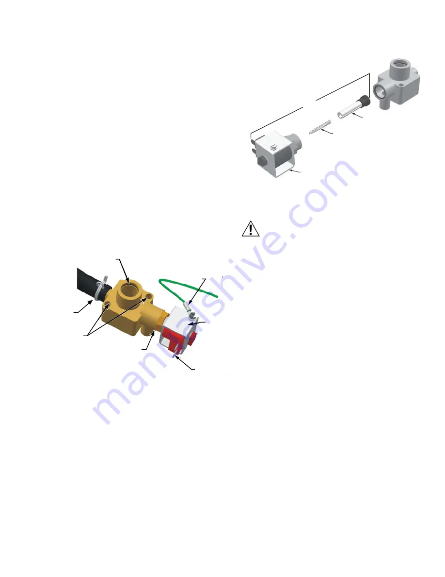
Fig. 23. Drain valve.

Fig. 24. Drain valve actuator assembly.

Installing the New Cylinder

CAUTION

Make sure the new cylinder is a HM700ACYL2. Use 

of any other model or remanufactured cylinders 

will void the HM700 warranty.

1.

Insert cylinder into drain valve. Tilt cylinder forward and 

fit end of steam hose to steam outlet. Tip cylinder back 

into place.

2.

Tighten hose clamp being careful not to over tighten and 

crush the plastic cylinder steam outlet.

3.

Attach color-coded cylinder plugs to the corresponding 

color-coded cylinder pin. Push down completely. 

Connect high water sensor plug. Spring-loaded plugs 

should fit snuggly onto the cylinder pin. Replace if they 

are loose or damaged.

4.

Re-fasten tie strap.

5.

Replace the humidifier cover and secure with two 

screws.

6.

Turn on power to humidifier with the external 

disconnect.

7.

Open supply water shut off valve.

8.

Turn the humidifier On/Off /Drain switch to On.

CYLINDER PORT

AND O-RING

GROUND

WIRE

SOLENOID

SPADE

CONNECTORS

BRASS NUT

(ACTUATOR)

SCREWS

HOSE AND 

HOSE CLAMP

MCR35700

M35707

SLEEVE AND 

SOLENOID

SPRING

(NOTE ORIENTATION)

PLUNGER

ACTUATOR

Содержание HM700A1000

Страница 1: ...tions without the need to change its configuration NOTE Because the humidifier is factory configured for optimal performance Honeywell strongly discourages changes to the jumpers or the potentiometer doing so will void the warranty and could damage the humidifier Contact Honeywell Customer Care for further information Before Installation 1 Ensure that available voltage and phase corresponds with h...

Страница 2: ...he HM700 produces steam at atmospheric pressure No devices which could block steam output should be connected to the steam outlet Steam lines must be installed so that no restriction can produce backpressure in the humidifier CAUTION Water quality The Honeywell HM700 requires a cold water connection from your home s main water supply between 30 100 PSIG A throttle valve may be necessary and a wate...

Страница 3: ...er will automatically fill to a higher water level to maintain full capacity during the life of the cylinder Eventually because of scale formation it will no longer be possible for the humidifier to reach its full capacity The HM700 software monitors this condition and when detected will stop operating and flash the yellow LED in a repeating sequence of 4 flashes DRAINS As steam is produced minera...

Страница 4: ...d 22 GPD when run on 240 V See Figures 15 for details on configuring the HM700 to run on a different voltage Table 3 contains AHRI recommendations for humidity requirements and Table 4 shows what humidifiers and output configuration will satisfy the humidification requirements Table 3 AHRI Recommended Humidity in gallons per day Optional 1 R HUM 2 HUM 3 C 4 N A 8 AP 19 Gf 20 Rf 21 N A 1 8 NPT to 1...

Страница 5: ...for servicing NOTE Do not mount on hot surfaces where freezing can occur vibrating surface or floor Mounting with Keyholes 1 The HM700 humidifier is wall mounted using a keyhole located on the back of the unit cabinetry 2 Use 8 x 2 in 5 cm screws mounted into 2x4 studs or better 2 screws are needed one for hanging the unit and one for securing so it will not lift off the keyhole 3 Install the top ...

Страница 6: ... ºF 1 to 20 ºC Install water shut off valve before humidifier to facilitate servicing The drain line should not end in a sink used frequently by personnel or where plumbing codes prohibit it Route to a floor drain or equivalent for safety reasons Ensure drain line is adequately sized to provide free and easy draining and that an air gap is installed as shown A restricted drain can cause cylinder w...

Страница 7: ... Fig 6 Fig 7 Distributor installed horizontally in a horizontal duct Fig 8 Distributor installed horizontally in a vertical duct Rotate the distributor 45º so that steam is discharged toward the center of duct in the direction of the air flow Fig 9 Distributor installed vertically in a horizontal duct This configuration is not recommended Part Number Description Notes HM700ADISTKIT Stainless Steel...

Страница 8: ...er the copper tube Fasten in place with the spring clamp Fig 10 Condensate return MAIN RULES FOR ATMOSPHERIC STEAM LINES Steam lines must not have any restrictions which could result in back pressure Follow recommended materials size and length see tables Install steam line in a vertical upwards fashion from the HM700 to the distribution nozzle Consult Figures 11 13 for other installation options ...

Страница 9: ...305 MINIMUM RADIUS CONDENSATE LINE SUPPORT BRACKETS 12 305 2 51 MINIMUM CONNECT STEAM HOSE TO CYLINDER CONDENSATE LINE 12 305 MINIMUM M35718 SUPPORT BRACKETS CONDENSATE TRAP TO DRAIN 12 305 MINIMUM RADIUS 12 305 MINIMUM BEFORE ANY BEND M35719 TO DRAIN OBSTRUCTION 12 305 MINIMUM 12 305 MINIMUM RADIUS 12 305 MINIMUM BEFORE ANY BEND SUPPORT BRACKETS USE FULL SIZE CONDENSATE TEE AT LOW POINT SLOPE LIN...

Страница 10: ...possible and remove excess Fig 15 Primary power connection NOTES Honeywell requires the use of a GFI circuit on this device to protect the homeowner from electrical shock When installed correctly the green wire should be removed from the drain valve The green wire comes pre installed from the factory to protect the homeowner in case of an improper installation or when it is not possible to retrofi...

Страница 11: ...idity drafts doorways sunlight or an overhang such as a shelf can affect reading Optional Outdoor Temperature Sensor not shown included with HumidPRO Mount outside in area representing air temperature Fig 16 Wiring the steam humidifier with a digital thermostat Fig 17 Wiring the steam humidifier with a mechanical thermostat NOTE If a Prestige VisionPRO Lyric or similar are used to control humidity...

Страница 12: ...ugh an On Off humidistat and other security devices in series Fused Disconnect Correct voltage amps phase per spec label optional Mounting Unit level Screws into structural member Steam Line Adequate slope No restrictions No kinks in hose Condensate traps on long runs High Limit On Off optional In series between terminals 1 and 2 Jumper between terminals 1 and 8 must be removed Note U or HUM termi...

Страница 13: ...is in normal operation mode 7 Check and adjust the control setpoint on the control and high limit humidistat 8 When the external humidistat generates a demand for humidity and the security loop is closed the green humidifying LED on the front of the humidifier will light up the power relay on the control board will engage the fill valve will activate after a delay and the cylinder will slowly fill...

Страница 14: ... action Green LED On Indicates steam is being produced Selecting a Relative Humidity Setpoint The optimum humidity setpoint depends on the reasons that a space is being humidified The ASHRAE Handbook HVAC Applications recommends specific design relative humidity for specific applications Health and Comfort The benefit of humidity is most pronounced for health and comfort in the 40 60 range A humid...

Страница 15: ...er components Steam Outlet Condensate Return Fill Cup Drain Valve Drain Canal Fill Valve Cylinder Cylinder Plug High Water Sensor Plug On Off Drain Switch Control Board Power Relay High Voltage Terminal Block Transformer Control Terminal Strip ...

Страница 16: ...s input and output connections to humidifier components Fill Cup Provides an air gap for backflow prevention Fill Valve Controls flow of water into humidifier High Voltage Terminal Block Primary power connection from remote disconnect to humidifier High Water sensor Plug Used to detect max water level in cylinder On Off Drain Switch Turns power on off to humidifier controller and drains the cylind...

Страница 17: ... not responsible for any damages resulting from or attributed to the failure to replace a spent cylinder see Manufacturer s Warranty NOTE Honeywell recommends keeping a replacement cylinder in stock throughout the humidification season This will prevent possible downtime when the humidifier reports cylinder end of life REPLACEMENT CYLINDER The label on the existing cylinder identifies the cylinder...

Страница 18: ...ith the external discon nect 5 Remove the two screws securing the front cover 6 Remove the cylinder plugs from the cylinder pins by pulling vertically 7 Using a flat screwdriver loosen the hose clamp where the hose is connected to the cylinder 8 Tip the top of the cylinder forward to pivot it out of the steam hose When free of steam hose lift the cylinder out NOTE The HM700 has a re usable tie str...

Страница 19: ... end of hose and reattach to valve Slide hose clamp back in place and place valve into drain pan 9 Secure valve with 2 screws to drain pan Fig 23 Drain valve Fig 24 Drain valve actuator assembly Installing the New Cylinder CAUTION Make sure the new cylinder is a HM700ACYL2 Use of any other model or remanufactured cylinders will void the HM700 warranty 1 Insert cylinder into drain valve Tilt cylind...

Страница 20: ...ty for an extended period of time This feature will reduce or prevent the possibility of corrosion of the electrodes and the accumulation of algae and bacteria growing in the cylinder The cylinder will remain empty until there is a call for humidity at which time the fill valve will open and refill the cylinder The unit will go through its normal process for optimum operation STARTING AFTER EXTEND...

Страница 21: ...to the manuals that were provided with the auxiliary equipment and to Table 8 Troubleshooting HM700 Faults on page 23 Table 7 General troubleshooting Symptom Cause Corrective Action s Nothing happens when On Off switch is turned on Fuse blown Check inline fuse between transformer and control board Incorrect Voltage Check voltage against spec label and correct Step Down Transformer not outputting 2...

Страница 22: ...quired Incorrect steam line installation Check that steam line has been installed with condensate traps and slope See Steam Lines and Condensate Return Instructions on page 8 Condensation in duct Installation clearances not observed Refer to distributor installation manual for required clearances Relocate distributor if required Design conditions changed Check supply air temperature and humidity t...

Страница 23: ...ing down the potentiometer Wrong cylinder installed Install correct cylinder model Cylinder Spent but not detected by software Replace the cylinder see maintenance chapter Condensate from other source Remove condensate returns other than from steam line Back pressure Eliminate back pressure 2 flashes No Current Fill valve activated for long time but high water level not reached Fill should be fast...

Страница 24: ... R HUM AP GF RF C HUM N A N A 120 L1 EXTERNAL INTERNAL 240 P ON OFF DRAIN SWITCH TRANSFORMER N A 120 L1 240 P S STATUS LAMPS G Y NOTE INSTALL JUMPER FROM PTO TERMINAL CORRESPONDING TO MAINS VOLTAGE HOT NEUTRAL GROUND HOT HOT GROUND 240 VAC 120 VAC NOTE DRY POINTS FOR FURNACE FAN ENABLE 24 V PILOT CONTROL ONLY N A FACTORY INSTALLED TERMINAL HUMIDITY CONTROL 24V HUM CALL M35721 ...

Страница 25: ...consumer Honeywell s sole responsibility shall be to repair or replace the product within the terms stated above HONEYWELL SHALL NOT BE LIABLE FOR ANY LOSS OR DAMAGE OF ANY KIND INCLUDING ANY INCIDENTAL OR CONSEQUENTIAL DAMAGES RESULTING DIRECTLY OR INDIRECTLY FROM ANY BREACH OF ANY WARRANTY EXPRESS OR IMPLIED OR ANY OTHER FAILURE OF THIS PRODUCT Some states do not allow the exclusion or limitatio...

Страница 26: ...HM700A1000 33 00118 01 26 ...

Страница 27: ...HM700A1000 27 33 00118 01 ...

Страница 28: ...nd Control Solutions Honeywell International Inc 1985 Douglas Drive North Golden Valley MN 55422 customer honeywell com U S Registered Trademark 2015 Honeywell International Inc 33 00118 01 M S 11 15 Printed in United States ...

Отзывы: