© 2017 Honeywell International Inc. All rights reserved. No part of this publication may be reproduced by any means without written permission from Honeywell. The information in this publication is believed to be accurate in all respects.
However, Honeywell cannot assume responsibility for any consequences resulting from the use thereof. The information contained herein is subject to change without notice. Revisions or new editions to this publication may be issued to
incorporate such changes. For patent information, see www.honeywell.com/patents.
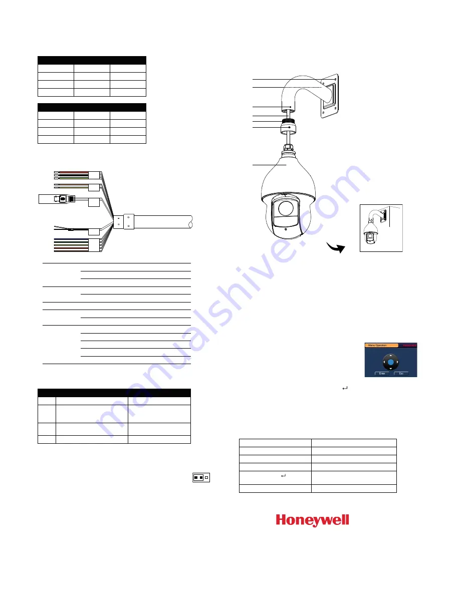
Setting the Baud Rate and Video Format
The baud rate and video format are set using the 4-position DIP switch.
Use the following tables as a reference:
Baud Rate
1
2
9600 bps
OFF
OFF
4800 bps
ON
OFF
2400 bps
OFF
ON
1200 bps
ON
ON
Video Format
3
4
CVI
OFF
OFF
TVI
OFF
ON
AHD
ON
OFF
SD
ON
ON
Connecting the Cables
Power
Red
24 V AC
Black
24 V AC
Yellow & Green
Earth
RS485
Yellow
A+
Orange
B-
Video Out
BNC
Audio
White
Audio IN
Black
Audio GND
Alarm
Blue
Alarm OUT 1
Green
Alarm COM1
Red
Alarm IN1
Brown
Alarm IN2
Yellow & Green
Alarm GND
Recommended Cables and Maximum Distances
Type
Recommended Cable
Maximum Distance
Power
18 AWG 2-conductor
153 ft (46.5 m)
Data
Cat5 24 AWG twisted pair (use
shielding in high electrical
interference locations)
5905 ft (1800 m) @ 2400 bps
3937 ft (1200 m) @ 4800 bps
2625 ft (800 m) @ 9600 bps
Video
RG-59/U coaxial cable with BNC
crimp, 75 ohm, copper conductor
750 ft (229 m)
Alarm
Belden 8205
10,000 ft (3048 m)
RS-485 Connection Guidelines
•
Data termination (120 ohm) is set at the rear of the camera, next to
the DIP switches. It is open by default, with the jumper over pins 2 and
3. To terminate the camera, place the jumper over pins 1 and 2 (see
figure at right).
•
In an RS485 bus, terminate the two endpoints to prevent signal reflection. If a
star topology is used, terminate all connected PTZ cameras and use an RS485
data distributor (such as HDCD8TP).
Note
: For more information, please refer to the HDZP30XD4 user guide (800-23522). The
guide is available for download from www.honeywellvideo.com.
Mounting the Camera
The wall mount weighs 1.08 lb (0.49 kg) and can be installed directly to a load-bearing
wall, or to a corner or pole using an appropriate adapter.
Important!
Ensure that the mounting surface can support at least three times the
combined weight of the camera and mount (at least 27.72 lb/12.57 kg).
Configuring the OSD Menu Settings
When the camera is connected to a Honeywell Performance Series DVR (HRHQXXXX/
HRHTXXXX), you can access and configure the camera’s on-screen display (OSD) menu
using either the HQA or RS485 control modes.
OSD Configuration: Up-the-Coax
Note:
The DVR’s PTZ control mode and protocol must be set to
HQA
(in
Main Menu >
Setting > System > PTZ
) for up-the-coax control of the OSD menu.
1.
Verify that the camera is connected to a Honeywell Performance Series DVR.
2.
Turn on the DVR, right-click to display the shortcut
menu, then click
Camera Menu
.
3.
Log on to the DVR as the admin user. The
Menu
Operation
window opens.
4.
Click
Enter
to display the camera’s OSD menu.
5.
To configure OSD settings, in the
Menu Operation
window, click the up or down arrows to move through
the menu list, click the left or right arrows to change
a setting, or click
Enter
to enter a submenu (
) or execute a command.
6.
After you have finished configuring the camera, scroll down to
Exit
, and then click
Enter
to exit the OSD menu. Right-click to close the
Menu Operation
window.
OSD Configuration: RS485
Note:
The DVR’s PTZ control mode must be set to
Serial
(in
Main Menu > Setting >
System > PTZ
) for RS485 control of the OSD menu.
Task
Action
To display the OSD menu
Call
Preset 95
.
To scroll through the OSD menu
Move the joystick up or down.
To change a setting
Move the joystick left or right.
To open a submenu (
) or
execute a command
Press
Iris +
(Iris Open).
To exit the OSD menu
Press
Iris –
(Iris Close).
Power
Audio
Alarm
RS485
Video
Out
1.
Loosen the mount locking
screw.
2.
Screw the adapter to the
mount.
3.
Tighten the mount locking
screw.
4.
Loosen the three locking
screws on the adapter.
5.
Feed the camera cables
through the mount.
6.
Attach the camera body to the
adapter and tighten the three
locking screws to secure the
camera body to the mount.
7.
Make connections of the
camera cables with the cables
fed through the wall.
8.
Attach the mount to the wall
using appropriate hardware.
4
6
1/3
5
2
7
8
Finished
1 2 3
www.honeywell.com/security
+1 800 323 4576 (North America only)
https://www.honeywellsystems.com/ss/techsupp/index.html
Document 800-23323 – Rev A – 08/2017


