2
Address 1
2
3
4
5
6
7
8
0
OFF OFF
OFF OFF OFF OFF OFF OFF
1
ON
OFF
OFF OFF OFF OFF OFF OFF
2
OFF ON
OFF OFF OFF OFF OFF OFF
3
ON
ON
OFF OFF OFF OFF OFF OFF
4
OFF OFF
ON
OFF OFF OFF OFF OFF
5
ON
OFF
ON
OFF OFF OFF OFF OFF
6
OFF ON
ON
OFF OFF OFF OFF OFF
7
ON
ON
ON
OFF OFF OFF OFF OFF
8
OFF OFF
OFF ON
OFF OFF OFF OFF
……
…………………………………………………………………
254
OFF ON
ON
ON
ON
ON
ON
ON
255
ON
ON
ON
ON
ON
ON
ON
ON
Baud Rate and Parity Setup
From Baud/Parity dip switches 1~4, 1 and 2 set the baud rate. Switches 3 and 4 set
the parity.
1
2
Baud rate
OFF
OFF
9600bps
ON
OFF
4800bps
OFF
ON
2400bps
ON
ON
1200bps
3
4
Parity
OFF
OFF
NONE
ON
OFF
EVEN
OFF
ON
ODD
ON
ON
NONE
Cable Connections
Power
Red
AC24V
Black
AC24V
Yellow & Green
Earth
RS485
Yellow
A+
Orange
B-
Video Out
BNC
Audio
White
Audio IN
Black
Audio GND
Alarm
Blue
Alarm OUT 1
Green
Alarm COM1
Red
Alarm IN1
Brown
Alarm IN2
Yellow & Green
Alarm GND
Note:
If you are using Honeywell Performance Series DVR (HRHHXXXX/HRHMXXXX)
and the HQA Protocol is selected, the PTZ can be directly controlled via the BNC cable.
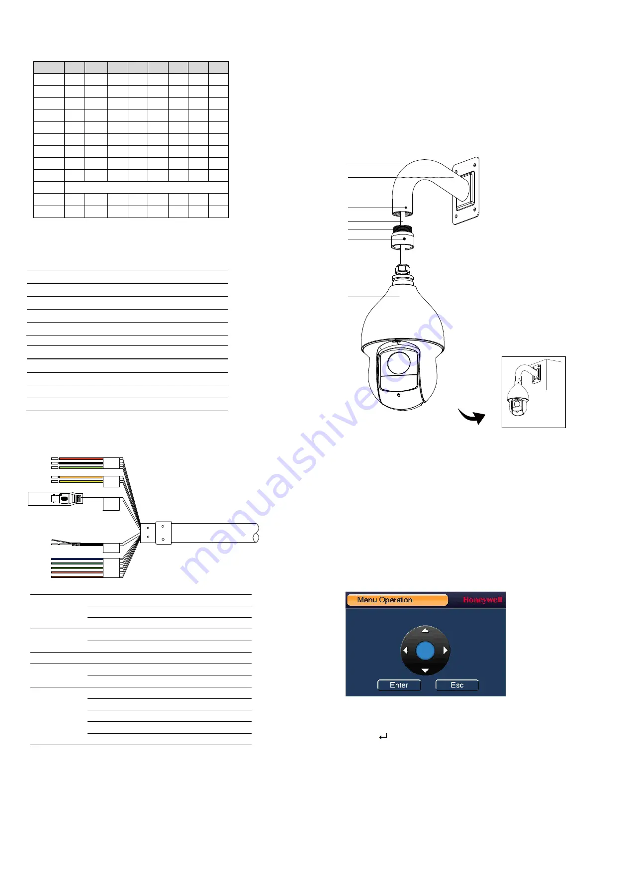
Installing a Wall Mount
The wall mount weighs 1.08 lb (0.49 kg) and can be installed directly to a load-bearing
wall, or to a corner or pole using an appropriate adaptor.
Important Notes:
Ensure that the mounting surface can support 3x the combined weight of the camera
and the mount (at least 27.72 lb/12.57 kg).
Configuring the PTZ Dome Camera
When the camera is connected to a Performance Series HQA DVR, you can configure the
camera’s settings using the camera’s on-screen display (OSD) menu.
Note:
The DVR’s PTZ protocol must be set to HQA for up-the-coax control of the OSD
menu.
To configure the camera settings
1.
Verify that the camera is connected to the DVR.
2.
Log on to the DVR as the admin user. The default user name is
admin
(case-
sensitive) and the default password is
1234
.
3.
Right-click to display the shortcut menu, and then click
Camera Menu
. A
dedicated menu operation interface appears.
4.
Click
Enter
to display the camera’s OSD menu.
5.
To configure the camera, click the up or down arrows to move through the menu
list, click the left or right arrows to change a menu setting, or click
Enter
to enter a
submenu (
) or execute a command.
6.
After you have configured the camera, right-click to exit the menu operation
interface.
Power
Audio
Alarm
RS485
Video
Out
1.
Loosen the mount locking
screw.
2.
Screw the adaptor to the
mount.
3.
Tighten the mount locking
screw.
4.
Loosen the three locking
screws on the adaptor.
5.
Feed the camera cables
through the mount.
6.
Attach the camera body to the
adaptor and tighten the three
locking screws to secure the
camera body to the mount.
7.
Make connections of the
camera cables with the cables
fed through the wall.
8.
Attach the mount to the wall
using appropriate hardware.
4
6
1/3
5
2
7
8
Finished


