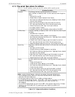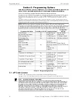
S3 Series UL Listing Document —
P/N LS10005-051GF-E:D3 3/09/2016
35
Separation of Circuits
Installation Wiring
2.15 Separation of Circuits
2.15.1 S3 Series, SLP-BB Cabinet, Class 2 Power-Limited/Non Power-Limited
Wiring Requirements
UL Standard 864, (Control Units for Fire Protective Signaling Systems), requires that a minimum of 1/4 inch
separation be maintained between Class 2 power-limited circuits and non power-limited circuits. The control
unit is designed so that the required separation between these circuits (Class 2 power-limited vs. non power-
limited) is maintained at the field wiring terminals.
In order to fully comply with the intent of these requirements, however, the minimum 1/4 inch separation must
also be maintained between the field wiring conductors of Class 2 power-limited circuits and non power-lim-
ited circuits. This may be accomplished by routing the field wiring as shown in Figure 2.15.1.1 and
Unless otherwise indicated on the unit, all field-wiring circuits are Class 2 power-limited except:
•
AC power circuit
•
Standby battery circuit
•
Telephone line connections
•
Master Box / Releasing
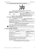
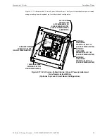
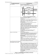
Figure 2.15.1.1 illustrates the S3 Series System, SLP-BB Cabinet, Class 2 power-limited and non-power-lim-
ited wiring extending from the DACT-E3, RPT-E3-UTP and SLC-PM/SLC95-PM modules.
Figure 2.15.1.1 S3 Series, SLP-BB Cabinet, Class 2 Power-Limited and
Non-Power-Limited Wiring
(Basic Bottom Level Circuit Board Configuration)
SLC CIRCUITS
FROM SLC-PM
(SYSTEM SENSOR) OR
SLC95-PM (APOLLO) TB1
(CLASS 2 POWER-LIMITED,
SUPERVISED)
DAC
T-E3
RPT-E
3-UT
P
FSL-E3
#1
SLP-E
3
NETWORK
USING FIBER
FROM FSL-E3 #2 J17 J2
(CLASS 2 POWER-LIMITED)
NETWORK
USING FIBER
FROM FSL-E3 #1 J2 & J1
(CLASS 2 POWER-LIMITED)
NETWORK
USING WIRE
FROM RPT-E3-UTP TB1
(CLASS 2 POWER-LIMITED)
AUXILIARY RS485
FROM DACT-E3 TB2
(CLASS 2
POWER-LIMITED)
TELEPHONE LINES
FROM DACT-E3 TB2
(CLASS 2
NON POWER-LIMITED)
TB1
TB2
TB1
TB1
TB1
FLP
S-7
J2
J1
J2
J1
FSL-E3 #
2
SLC-PM
#2
SLC-PM
#1

