


32
S3 Series UL Listing Document —
P/N LS10005-051GF-E:D3 3/09/2016
Installation Wiring
Releasing Device Circuit
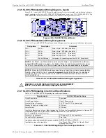
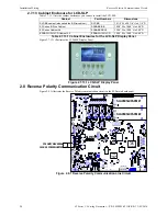
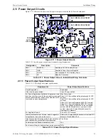
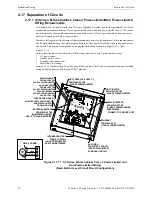
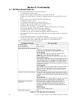
2.12 Releasing Device Circuit
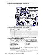
Figure 2.12.1 illustrates the Releasing Device circuit on the SLP main board panel.
Figure 2.12.1 Releasing Device Circuit
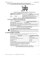
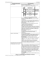
Table 2.12.1 lists the Releasing Device circuit terminal designations.
2.12.1 Releasing Device Circuit Specifications
Table 2.12.1.1 lists the Releasing Device Circuit specifications.
SLP-E3
SLC-PM/SLC95-PM #2
SLC-PM/SLC95-PM #1
TB4
TB3
TB2
TB1
TB5
BAR CODE
LABEL
PRODUCT
SERIAL NUMBER
PRODUCT
DATE CODE
LABEL
ETHERNET
J2
W1
J7
RELEASING DEVICE CIRCUIT
(NON POWER-LIMITED)
B- B+
J1
J1
J4
J5
J6
Designation
Description
Comments
TB2-5
MUNI +
Negative Output to Local Energy City Box, Remote Station or Releasing
Solenoid. (See Figure 2.12.1)
TB2-6
MUNI -
Negative Output to Local Energy City Box, Remote Station or Releasing
Solenoid. (See Figure 2.12.1)
Table 2.12.1 Releasing Device - Installation Wiring Terminals
Requirements
Releasing Device Specifications
Circuit supervision:
Supervised
Circuit Power Requirements:
Class 2 Power-Limited
Maximum voltage, rated current, and frequency:
27.5 VDC, 0.081 A
Maximum current:
0.700 A
Specific releasing devices by Manufacturer’s name and
model for connection to the circuit.
Refer to the Compatibility Addendum to Gamewell-FCI
Installation/Operation Manuals UL File S1869 Vol. 8C,
P/N: 9000-0427-L8.
Impedance values for testing at which ground faults are
annunciated when ground faults affect the operation.
Zero Ohms
Table 2.12.1.1 Releasing Device Specifications
NOTE:
Releasing activation upon alarm may optionally be delayed by user Configuration
Programming using CAMWorks.