background image

Mark V and Mark VII EGPWS Pilot’s Guide 


060-4241-000 

Smart Runway


®


Rev H, August 2011 

79 

Runway 

Entry and 

Occupancy 

Continued 

RAAS does not account for operational data such as 
NOTAMs that refer to areas of runway that are not available 
(e.g., due construction, snow removal, etc.). Crews should be 
cognizant of any NOTAMs and other published restrictions in 
effect. 

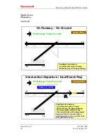
The routine “On runway” message advisory is appended by 
runway length remaining in either feet or metres, e.g., “

On 

runway three-four-left, two-thousand remaining

”. The 

"remaining" element of the message refers to the runway 
distance remaining in the EGPWS database to the nearest 100 
feet (or 100 metres for a metric option). Note  that the unit 
(feet or metres) is not annunciated. The unit of length used by 
RAAS can be confirmed by performing an EGPWS self-test 
(See “Operational Availability” section). 

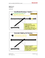
If caution is enabled, 

“Caution Short Runway, Short Runway”


is heard after the existing aural when groundspeed exceeds 40 
knots.


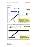
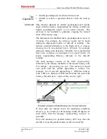
Dissimilar references to the runway heading during the 
Approaching Runway and the On Runway advisories are a cue to 
a potentially unusual situation. In this example assume that the 
aircraft is cleared for an intersection departure at Alpha 2 for 
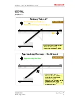
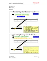
runway 16R. The "

Approaching-one-six right

" advisory is 

provided as the aircraft approaches the runway at Alpha 2. 
However, an inadvertent turn on to runway 34L (as opposed to 
16R) implies that  runway identifier for the Insufficient Runway 
Length Advisory is runway "34L". If the crew correctly turns 
onto runway 16R, the runway identifier for the routine On 
Runway Advisory is "16R". Note that a third reference to the 
"intended" runway for departure, in this example, is a clearance 
for take-off from runway "16R" from ATC.  


Содержание EGPWS MK V

Страница 1: ...FILE ONLY Release 08 Aug 2011 14 50 02 MST Printed on 01 Mar 2013 ...

Страница 2: ......

Страница 3: ... the express written permission of Honeywell International Inc is prohibited For further information contact Airlines and Avionics Products AAP Address 15001 N E 36th Street Redmond WA 98073 Telephone 425 885 8367 OR Honeywell Global Customer Care Telephone 800 601 3099 U S A Canada Telephone 602 365 3099 International Web site http portal honeywell com wps portal aero The information contained in...

Страница 4: ......

Страница 5: ...able of Contents Rev H August 2011 i TABLE OF CONTENTS SECTION 1 INTRODUCTION 1 SECTION 2 SYSTEM DESCRIPTION 5 SECTION 3 OPERATIONAL PROCEDURES 46 SECTION 4 DEFINITIONS 59 SMARTRUNWAY PILOT GUIDE 61 SMARTLANDINGTM PILOT GUIDE 99 Request for Information 117 ...

Страница 6: ...Mark V and Mark VII EGPWS Pilot s Guide Table of Contents 060 4241 000 ii Rev H August 2011 Blank Page ...

Страница 7: ...aft with the EGPWS The information in this document is intended as a general explanation of the Honeywell EGPWS It contains a general description of system performance assuming identified options are active and highlights deviations in system performance resulting when a feature is disabled What is the EGPWS The EGPWS is a Terrain Awareness and Alerting system providing terrain alerting and displa...

Страница 8: ...le conflict alerting and display Additionally when TAD is enabled Obstacles are graphically displayed similar to terrain This feature is an option enabled by program pins during installation Envelope Modulation is a feature utilizing a database of airport approach and departure profiles to tailor EGPWS alerts at certain geographic locations to reduce nuisance alerts and provide added protection A ...

Страница 9: ...akeoff flap configuration These features are optional enabled by PCMCIA card available in 230 230 or later versions The SMARTLANDING TM option provides visual and aural annunciations that supplement flight crew awareness of un stabilized approaches altimeter setting problems landing long and select RAAS advisories These features are optional enabled by PCMCIA card available in 230 230 or later ver...

Страница 10: ...Mark V and Mark VII EGPWS Pilot s Guide Introduction 060 4241 000 4 Rev H August 2011 Blank Page ...

Страница 11: ...rrain Clearance 14 Mode 4A 14 Mode 4B 15 Mode 4C 16 Mode 5 Excessive Deviation Below Glideslope 18 Mode 6 Advisory Callouts 19 Mode 7 Windshear Alerting 24 Enhanced Functions Envelope Modulation 26 Terrain Clearance Floor 26 Runway Field Clearance Floor 28 Terrain Look Ahead Alerting 29 Terrain Alerting and Display 30 Non Peaks Display 30 Pop Up and Auto Range 33 Peaks Display 33 TAD TCF INOP Annu...

Страница 12: ...windshear threshold is exceeded EGPWS Database The EGPWS adds to these 7 basic functions the ability to compare the aircraft position to an internal database and provide additional alerting and display capabilities for enhanced situational awareness and safety hence the term Enhanced GPWS The EGPWS internal database consists of four sub sets 1 A worldwide terrain database of varying degrees of res...

Страница 13: ...th this information the EGPWS is able to present a graphical plan view of the aircraft relative to the terrain and advise the flight crew of a potential conflict with the terrain or obstacle Conflicts are recognized and alerts provided when terrain violates specific computed envelope boundaries on the projected flight path of the aircraft Alerts are provided in the form of visual light annunciatio...

Страница 14: ...aution lights and SINKRATE SINKRATE alert annunciation Additional SINKRATE SINKRATE messages will occur for each 20 degradation in altitude During the time that the Sinkrate aural is inhibited and the alert lamp is ON the Mode 5 aural Glideslope is allowed to annunciate for excessive glideslope deviation below the beam Penetration of the inner boundary activates the EGPWS warning lights and change...

Страница 15: ...right at certain airports to minimize nuisance alerts or warnings Steep Approach Bias The EGPWS offers a Steep Approach option for given aircraft types that desensitizes the alert boundaries to permit steeper than normal approaches without unwanted alerts If Steep Approach is selected active then the cockpit self test is inhibited if the aircraft is on the ground For Airbus A318 319 320 321 with v...

Страница 16: ...es to penetrate the envelope the EGPWS warning lights will illuminate and the aural warning message PULL UP is repeated continuously until the warning envelope is exited Note Pull Up may be preceded by Whoop Whoop in some configurations based on the audio menu option selected Upon exiting the warning envelope if terrain clearance continues to decrease the aural message TERRAIN will be given until ...

Страница 17: ...ersion 210 210 and later models the Mode 2A upper limit is reduced to 1250 feet 950 feet with version 218 218 and later for all airspeeds when the Terrain Alerting and Display TAD function is enabled and available This is due to the enhanced alerting capability provided with TAD resulting from high integrity GPS Altitude and Geometric Altitude data The Mode 2A envelope is lowered in order to reduc...

Страница 18: ...than 2 dots It is also active during the first 60 seconds after takeoff With version 210 210 and later models Mode 2B is selected when the aircraft is within 5 NM 10 NM with version 218 218 and later and 3500 feet of the destination airport independent of configuration and the Terrain Alerting and Display TAD function is enabled and available This is due to the enhanced alerting capability provide...

Страница 19: ...e aural PULL UP messages are suppressed and the aural message TERRAIN is repeated until the envelope is exited MODE 3 Altitude Loss After TakeOff Mode 3 provides alerts for significant altitude loss after takeoff or low altitude go around less than 245 feet AGL or 150 feet depending on aircraft type with gear or flaps not in the landing configuration The amount of altitude loss that is permitted b...

Страница 20: ... To reduce nuisance alerts caused by over flying another aircraft the upper limit of the Mode 4A B alerting curve can be reduced from 1000 to 800 feet This occurs if the airplane is above 250 knots with gear and flaps not in landing configuration and a sudden change in Radio Altitude is detected This is intended to eliminate nuisance alerts while flying a holding pattern and an aircraft over fligh...

Страница 21: ...t messages occur for each 20 degradation in altitude EGPWS caution lights extinguish and aural messages cease when the Mode 4A alert envelope is exited If the Aural Declutter feature is disabled mode 4A alert messages are repeated continuously until the Mode 4A envelope is exited MODE 4B Mode 4B is active during cruise and approach with gear down and flaps not in the landing configuration Below 10...

Страница 22: ...ot If the aircraft s Radio Altitude decreases to the value of the Minimum Terrain Clearance MTC the EGPWS caution illuminates and the aural message TOO LOW TERRAIN is enunciated For either Mode 4B alert subsequent alert messages occur for each 20 degradation in altitude EGPWS caution lights extinguish and aural messages cease when the Mode 4B alert envelope is exited If the Aural Declutter feature...

Страница 23: ...ro feet As the aircraft ascends the MTC is increased to 75 of the aircraft s Radio Altitude averaged over the previous 15 seconds This value is not allowed to decrease and is limited to 500 feet AGL for airspeed less than 190 knots Beginning at 190 knots the MTC increases linearly to the limit of 1000 feet at 250 knots If the aircraft s Radio Altitude decreases to the value of the MTC the EGPWS ca...

Страница 24: ...slope deviation cause additional GLIDESLOPE messages enunciated at a progressively faster rate The second level alert occurs when below 300 feet Radio Altitude with 2 dots or greater glideslope deviation This is called a hard alert because a louder GLIDESLOPE GLIDESLOPE message is enunciated every 3 seconds continuing until the hard envelope is exited The caution lights remain on until a glideslop...

Страница 25: ...limbs above 2000 feet AGL 1000 feet AGL for current Boeing production aircraft An alternate glideslope cancel switch allows for manually canceling Mode 5 alerting at any time and any altitude The cancel is reset by again pressing the cancel switch or automatically if gear or flaps are raised or the aircraft is on the ground Due to the nature of the alternate cancel switch this method requires that...

Страница 26: ... FOUR HUNDRED 400 THREE HUNDRED 300 TWO HUNDRED 200 APPROACHING MINIMUMS DH 80 b APPROACHING DECISION HEIGHT DH 100 b PLUS HUNDRED DH 100 b FIFTY ABOVE DH 50 b MINIMUM DH b MINIMUMS DH b MINIMUMS MINIMUMS DH b DECISION HEIGHT DH b DECIDE DH b ONE HUNDRED 100 One Hundred Tone 2 second 700 Hz 100 EIGHTY 80 SIXTY 60 FIFTY 50 FORTY 40 THIRTY FIVE 35 Thirty Five Tone 1 second 1400 Hz 35 THIRTY 30 TWENT...

Страница 27: ...not all EGPWS installations can utilize these callout options Due to the variety of altitude callout choices available it is not possible to identify every combination in this guide Refer to an appropriate Airplane Flight Manual or EGPWS Airplane Flight Manual Supplement for callout identification in a specific application or contact Honeywell Smart 500 Foot Callout Another feature available in th...

Страница 28: ...supporting Air Transport Business or Military aircraft types only Air Transport and Business aircraft types are addressed below Business Bank Angle One envelope is defined for turbo prop and business jet aircraft see graph below Bank angles in excess of 10 between 5 and 30 feet 10 to 40 between 30 and 150 feet 40 to 55 between 150 and 2450 feet 55 above 2450 feet produce the bank angle advisory sh...

Страница 29: ...d and then again only if 45 is exceeded If the roll rate exceeds the audio callout time then the bypassed limit is not indicated Also when any one of the thresholds is exceeded the bank angle must reduce below 30 for the process to reset before additional Bank Angle Advisories can be provided For example if greater than 40 is obtained before the 35 callout is complete another callout is provided o...

Страница 30: ...rts are given if an increasing headwind or decreasing tailwind and or a severe updraft exceeds the defined threshold These are characteristic of conditions preceding an encounter with a microburst A Windshear Caution if enabled results in illumination of amber Windshear Caution lights and may if separately enabled also be accompanied by the aural message CAUTION WINDSHEAR The lights remain on for ...

Страница 31: ... windshear event is encountered The threshold is adjusted as a function of available climb performance flight path angle airspeeds significantly different from normal approach speeds and unusual fluctuations in Static Air Temperature typically associated with the leading edge of a microburst The Windshear Warning envelope is illustrated in the figure shown on page 25 Mode 7 Windshear alerting is a...

Страница 32: ...s 1 2 and 4 are desensitized at other locations to prevent nuisance alerts that result from unusual terrain or approach procedures In all cases very specific information is used to correlate the aircraft position and phase of flight prior to modulating the envelopes Terrain Clearance Floor The Terrain Clearance Floor TCF function enabled with TAD enhances the basic GPWS Modes by alerting the pilot...

Страница 33: ... 3 to 1 nm providing greater protection against landing short events With version 218 218 and later models the envelope bias factor is reduced to 1 4 nm if runway and position data is of high integrity Terrain 4 NM 12 NM 15 NM 400 AGL 700 AGL Terrain 245 foot curve expansion on runway sides only applicable to 210 210 and on RUNWAY ENVELOPE BIAS FACTOR ENVELOPE BIAS FACTOR 45 245 FT 245 FT CONVENTI...

Страница 34: ... the RFCF envelope is moved from 1nm to 1 2nm if runway and position data is of high integrity 1 5 Krf nm Minimum Runway Field Clearance ft RFCF Ceiling 300 ft above field Krf RFCF Alert Area Runway End Field Elevation 5 0 nm Outer Limit No Lower Limit RFCF Alert Envelope 5500 5000 4500 4000 3500 3000 2500 2000 1500 2 1 0 1 2 3 4 5 6 7 Distance to Center of Runway nm Altitude Elevation ft RFCF Ale...

Страница 35: ... flight path angle and the look down distance a function of the aircraft s altitude with respect to the nearest or destination runway This relationship prevents undesired alerts when taking off or landing The look ahead distance is a function of the aircraft s speed and distance to the nearest runway A terrain conflict intruding into the caution ribbon activates EGPWS caution lights and the aural ...

Страница 36: ...ities There are two types of TAD displays depending on the options selected The original type provides a terrain image only when the aircraft is 2000 feet or less above the terrain A second type called Peaks enhances the display characteristics to provide a higher degree of terrain awareness independent of the aircraft s altitude available for selected display types in version 206 206 with additio...

Страница 37: ...the terrain database then this area is displayed in a low density magenta color Terrain more than 2000 feet below the aircraft or within 400 vertical feet of the nearest runway elevation is not displayed black With version 218 218 or later the transition to black may occur below 400 feet based on runway and terrain database integrity for a given area When a caution alert is triggered the terrain o...

Страница 38: ...bstacle e g a single tower to be better seen on the display The transition between green and yellow is below the aircraft in order to account for altimetry and or terrain obstacle height errors Also the transition altitudes between colors are biased upward proportional to the descent rate when greater than 1000 feet per minute This provides approximately a 30 second advance display of terrain Esse...

Страница 39: ...of the highest and lowest terrain obstacle elevations currently displayed The display of additional solid or lower density color bands including the addition of the graphic representation of sea level 0 feet MSL With Terrain Display selected on digital values representing the highest terrain obstacle elevation and the elevation for the bottom of the lowest color band are displayed These are based ...

Страница 40: ... identical to the standard display with the exception of the addition of sea level when supported by the display Note some displays do not support cyan blue and will not display sea level in this case Note Differences may exist between the highest terrain obstacle being displayed and the digital elevation value color of the Peaks numbers at or near the top and sides of the display The following il...

Страница 41: ...Mark V and Mark VII EGPWS Pilot s Guide 060 4241 000 System Description Rev H August 2011 35 PEAKS DISPLAY Continued The following illustrate the Peaks display at a high relative altitude ...

Страница 42: ... 1000 feet above aircraft altitude Solid Green Peaks only Highest terrain not within 500 250 with gear down feet of aircraft altitude May appear with dotted yellow terrain when the aircraft altitude is within 500 feet 250 feet with gear down of terrain Top 5 of Range High Density Green Fill Terrain Obstacle that is 500 250 with gear down feet below to 1000 below aircraft altitude Peaks only Terrai...

Страница 43: ...e condition during the high enroute phase of flight Geometric Altitude Based on GPS altitude geometric altitude is a computed pseudo barometric altitude Above Sea Level ASL designed to reduce or eliminate errors potentially induced in Corrected Barometric Altitude by temperature extremes non standard pressure altitude conditions and altimeter miss sets This ensures an optimal EGPWS Terrain Alertin...

Страница 44: ...ic Altitude function is fully automatic and requires no pilot action Weather Radar Auto Tilt In 210 210 and later versions the EGPWC computes a optimum Weather Radar tilt angle based on the aircraft altitude ASL and the terrain elevation ahead of the aircraft This is output and available to a compatible Weather Radar system so that the tilt angle may be automatically set for optimum operation Aura...

Страница 45: ...ms Decision Height or Decide b May also be Approaching Decision Height Fifty Above Plus Hundred c Message is dependent on aircraft type or option selected d Windshear detection alerts provided for some aircraft types e Audio alert may or may not be enabled f May also be Terrain Ahead Terrain Ahead g May also be Obstacle Ahead Obstacle Ahead h May also be Terrain Ahead Pull Up i May also be Obstacl...

Страница 46: ... U T P R O C E S S I N G OPTIONAL NON TSO FUNCTIONS ALTITUDE CALLOUTS RUNWAY AWARENESS APPROACH MONITOR ALTIMETER MONITOR TAKEOFF FLAP MONITOR LONG LANDING MONITOR The EGPWS utilizes signals from the following systems Air Data Uncorrected and corrected Barometric Altitude Altitude rate Computed Airspeed True Airspeed and Static Air Temperature are provided by Air Data system Radio Altitude Radio A...

Страница 47: ...ource capable of providing Latitude fine and Longitude fine data VHF Nav Receiver Glideslope Localizer ILS Tuned Selected Runway Heading Terrain Display System Display range and if available the Hazard Bus from a Predictive Windshear System PWS If EFIS the EFIS display mode is used in some configurations AOA Vane or Stall Warning Discretes AOA Stick Shaker Margin Discrete inputs are used for syste...

Страница 48: ...Terrain video is generated by the EGPWC based on the aircraft s current position relative to the surrounding terrain This video is presented to a Weather Radar indicator EFIS display or a dedicated display unit Options The EGPWC uses program pin discrete inputs to define the installation configuration and option selection Software upgrades Reloadable Customer Definitions RCD are also available for...

Страница 49: ...udio alerts Lamp Format One of two lamp formats are available Lamp Format 1 provides only Mode 5 Glideslope alerts to the caution amber lamp output and all other alerts except Windshear and Mode 6 callouts to the warning red lamp output Lamp Format 2 provides all Pull Up warning alerts to the warning red lamp output and all caution alerts to the caution amber lamp output FAA requirement for new in...

Страница 50: ...urse approaches Altitude Callout Enable Enables Mode 6 Callouts Mode 6 Low Volume Reduces Mode 6 volume an additional 6 dB This is typically hardwired or connected to an external switch TAD and TCF Inhibit Cockpit switch to disable all TAD and TCF functions FAA requirement Audio Inhibit disables all EGPWS audio outputs Steep Approach Enable Enables Steep Approach Mode 1 Excessive Descent Rate aler...

Страница 51: ...Mark V and Mark VII EGPWS Pilot s Guide 060 4241 000 System Description Rev H August 2011 45 Blank Page ...

Страница 52: ...st 2011 SECTION 3 OPERATIONAL PROCEDURES System Constraints 46 System Activation 48 EGPWS Self Test 49 Normal Procedures 53 Caution Alerts 55 Warning Alerts 55 Glideslope Alerts 56 Advisory Callouts 56 Windshear Caution 56 Windshear Warning 56 Abnormal Procedures 57 Emergency Procedures 58 ...

Страница 53: ...enhanced functions are automatically inhibited with a resultant Terrain inoperative or unavailable indication TAD TCF functions should be manually inhibited Within 15 nm on approach to an airport or runway that is not in the airport runway database to avoid unwanted alerts During QFE operations if GPS data is unavailable or inoperative When the TAD TCF functions are inhibited and the EGPWS is othe...

Страница 54: ...g normally EGPWS Radio Altimeter Air Data ILS or Glideslope Receiver IRS AHRS VG attitude GPS FMS or IRS position Landing gear Landing flaps Stall warning or AOA windshear only Weather Radar EFIS or a dedicated terrain display if terrain obstacle display enabled In the event that required data for a particular function is not available then that function is automatically inhibited and annunciated ...

Страница 55: ...nputs detected by the EGPWC Level 4 Fault History provides an historical record of the internal and external faults detected by the EGPWC Level 5 Warning History provides an historical record of the alerts given by the EGPWS Level 6 Discrete Test provides audible indication of any change to a discrete input state A level 1 Go No Go Test is normally performed by flight crews as part of preflight ch...

Страница 56: ...st Actual annunciation nomenclature and sequence may differ depending on the installation GPWS INOP W S INOP and TERR INOP annunciators turn on Amber caution BELOW G S or GPWS annunciators turn on GLIDESLOPE is announced over speaker Amber annunciators turn off G S CANCEL annunciators turn on if installed G S CANCEL annunciators turn off Red warning PULL UP or GPWS annunciators turn on PULL UP is ...

Страница 57: ...g Monitor Takeoff Flap Configuration Monitor and or Approach Monitor are INOP or Inhibited the following message may be announced over the speaker RUNWAY AWARENESS INOP APPROACH MONITOR INOP FLAP MONITOR INOP ALTIMETER MONITOR INOP If Low Airspeed Monitor is enabled the following message may be announced over the speaker AIRSPEED LOW AIRSPEED LOW INHIBITED AIRSPEED LOW INOP GPWS INOP W S INOP and ...

Страница 58: ... V and Mark VII EGPWS Pilot s Guide Operational Procedure 060 4241 000 52 Rev H August 2011 indicated or observed For more specific information refer to an applicable AFM or EGPWS AFMS or contact Honeywell ...

Страница 59: ...conditions mode 5 Descent below predefined altitudes or excessive bank angle mode 6 Severe windshear conditions mode 7 Runway Awareness and Advisory System RAAS Unstable approaches MON Altimeter mis settings MON Incorrect takeoff flap settings MON Landing Long MON Low Airspeed MON These consist of warning caution and advisory alerts based on the detection alert threshold penetration The following ...

Страница 60: ...TCF TOO LOW GEAR or FLAPS 4 Altitude callouts 6 SINK RATE 1 DON T SINK 3 GLIDESLOPE 5 BANK ANGLE 6 FLAPS pause FLAPS or FLAPS FLAPS MON TOO HIGH TOO HIGH MON TOO FAST TOO FAST MON UNSTABLE UNSTABLE MON ALTIMETER SETTING MON AIRSPEED LOW MON FLAPS FLAPS MON1 LONG LANDING LONG LANDING or DEEP LANDING DEEP LANDING MON CAUTION TAXIWAY CAUTION TAXIWAY RAAS CAUTION SHORT RUNWAY SHORT RUNWAY RAAS CAUTION...

Страница 61: ...ly position throttles for maximum rated thrust Apply maximum available power as determined by emergency need The pilot not flying if applicable should set power and ensure that TO GA power and modes are set 2 If engaged disengage the autopilot and smoothly but aggressively increase pitch toward stick shaker or Pitch Limit Indicators PLI to obtain maximum climb performance 3 Continue climbing until...

Страница 62: ... weather factors the Windshear Caution should be considered in determining the advisability of performing a go around Wind and gust allowances should be added to the approach speed increasing thrust if necessary It may be necessary to disengage autopilot or auto throttle Avoid getting low on the approach glidepath or reducing the throttles to idle Windshear Warning When a Windshear warning occurs ...

Страница 63: ...y activating the FLAP OVER RIDE switch to eliminate related unwanted alerts This requires manual deactivation Mode 4 Unsafe Terrain Clearance Mode 4 alerts can be reduced by activation of the FLAP OVER RIDE switch or GEAR OVER RIDE This is generally recommended when performing approaches with less than normal landing flaps selected or landing gear not down This requires manual deactivation Mode 5 ...

Страница 64: ...ode 5 inhibiting Note Implementation of the Glideslope Cancel and or Inhibit inputs to the EGPWS varies Verify a particular application to determine the implementation used Terrain Alerting and Clearance Floor Pressing the Terrain Inhibit switch inhibits TAD and TCF alerting and display including Obstacles and Peaks when enabled This is used when position accuracy is inadequate or when operating a...

Страница 65: ...ment System EGPWC S Enhanced Ground Proximity Warning Computer System FAA Federal Aviation Administration FMS Flight Management System FPM Feet Per Minute F W Fail Warning GPS Global Positioning System GPWS Ground Proximity Warning System G S Glideslope HDOP Horizontal Dilution of Precision HFOM Horizontal Figure of Merit HIL Horizontal Integrity Limit Hz Hertz cps ICD Interface Control Document I...

Страница 66: ...ates airspace by all aircraft above FL180 QNH The more common method of setting the altimeter to compensate for changes in barometric pressure Pilot receives information from airfield adjusts his altimeter accordingly and the altimeter will read airfield elevation at touchdown RAAS Runway Awareness and Advisory System RAIM Receiver Autonomous Integrity Monitoring RCD Reloadable Customer Definition...

Страница 67: ...ILOT GUIDE RUNWAY AWARENESS AND ADVISORY SYSTEM RAAS TABLE OF CONTENTS SECTION 1 Introduction 62 SECTION 2 RAAS Quick Reference 67 SECTION 3 System Operation Description 74 SECTION 4 RAAS Options 92 SECTION 5 Audio Levels 93 SECTION 6 Operational Availability 94 SECTION 7 Frequently Asked Questions 96 ...

Страница 68: ...rements and procedures with respect to the operation of aircraft with the EGPWS and RAAS The information in this document is intended as a general explanation of the Honeywell RAAS It contains a description of system performance assuming the identified options are active Why RAAS It is well recognized that runway incursions and overruns are a high profile operational safety issue worldwide For exa...

Страница 69: ... outs How Does RAAS Work The RAAS uses aircraft inputs within the EGPWS such as GPS position heading groundspeed and a runway database to generate the aural annunciations shown in the tables below Note that GPS availability is a requirement for the operation of RAAS Aircraft position is referenced to the GPS antenna position RAAS does not have knowledge of taxiways Automatic Terminal Information S...

Страница 70: ... e g Approaching three four right three thousand remaining 1 If caution is enabled additional aural is Caution Short Runway Short Runway Taxiway Landing 1 Awareness that the aircraft is determined to be on Approach and is not aligned with a runway Caution Taxiway Caution Taxiway Take off Flap Monitor 1 Awareness of improper flap setting when the aircraft is lined up on a runway in advance of take ...

Страница 71: ... in detail in the RAAS Options section of this Pilot Guide Appropriate flight crew actions to RAAS advisories are If in doubt stop VERIFY POSITION and contact ATC for assistance if necessary Do not hesitate to request progressive taxi instructions If the advisory is in conflict with expectations VERIFY POSITION contact ATC for assistance if necessary Consideration should be given to a go around in...

Страница 72: ...RAAS operational availability is integrated into the existing EGPWS fault monitoring and self test functions Consistent with approved EGPWS self test design the loss of RAAS functions is indicated on ground only during a self test There is no automatic annunciation of the loss of RAAS functionality RAAS status can also be displayed on the terrain display This is active only when the aircraft is on...

Страница 73: ...ay Take off Taxi Operations Conditions for advisory caution Aircraft not on runway Groundspeed exceeds 40 kts 34L 16R 34R 16L 11 29 Approaching One One Approaching Runway On Ground Taxi Operations Conditions for advisory Advisory depends on aircraft groundspeed heading and nearest runway end Earlier call out at higher speeds Inhibited above 40 knots No distraction during take off landing ground ro...

Страница 74: ...ers onto a runway Within 20 deg Of runway heading 34L 16R 34R 16L 11 29 On Runway Three Four Left Six Hundred Remaining Intersection Departure Insufficient Rwy Runway Entry Conditions for advisory Aircraft enters onto a runway Within 20 deg Of runway heading Runway length available is less than nominal take off runway length Operator defined nominal runway length in metres or feet confirm units us...

Страница 75: ...itions for caution All conditions for a non routine Insufficient Runway advisory are satisfied and Runway length available is less than nominal take off runway length Aircraft groundspeed 40 knots 34L 16R 34R 16L 11 29 On Runway Three Four Left On Runway Three Four Left Extended Holding On Runway Runway Occupancy Conditions for advisory Aircraft on runway Within 20 deg Of runway heading Waiting in...

Страница 76: ...0 0 R e m a i n i n g 3 0 0 R e m a i n i n g 1 0 0 R e m a i n i n g Example in metres 34L 16R 34R 16L 11 29 Approaching Three Four Left Approaching Runway In Air Approach Conditions for advisory Between 750 and 300 feet above Field Elevation AFE Within 3 nautical miles of the approach end of runway Track aligned within 20 deg of runway heading and Within 200 feet plus runway width of runway cent...

Страница 77: ...s less than nominal landing runway length Operator defined nominal runway length in metres or feet RCD option to annunciate unit of measurement selected Example in feet 34L 16R 34R 16L 11 29 Approaching Three Four Right Three Thousand Available Caution Short Runway Short Runway Approaching Runway In Air Caution Approach Conditions for caution All conditions for a non routine Approaching Short Runw...

Страница 78: ...16R 11 16R 34L 34R 16L 29 4 0 0 0 R e m a i n i n g Distance Remaining Landing and Roll out Landing Conditions for advisory Aircraft on above last half of runway or a specified distance from runway end Groundspeed exceeds 40 kts Call suppressed during go around above 100 ft radio altitude or climb rate greater than 450 fpm Operator defined units in metres or feet confirm units using EGPWS self tes...

Страница 79: ...nway heading 100 feet or 30 m of runway remaining Groundspeed below 40 kts Operator defined units in metres or feet confirm units using EGPWS self test 100 Remaining Example in feet 16R 11 34L 16R 34R 16L 11 29 On Runway Three Four Left Flaps Flaps Take off Flap Monitor Runway Entry Conditions for advisory Aircraft enters onto a runway Within 20 deg Of runway heading Flap handle not in a valid tak...

Страница 80: ...all RAAS advisories have a lower priority than any existing EGPWS alert including radio altitude call outs Taxi Operations Taxiway Take Off Advisory A Honeywell runway incursion study indicates that 7 of incidents during takeoffs and landings were from onto a taxiway The purpose of the Taxiway Take Off Advisory is to enhance crew awareness of excessive taxi speeds or a take off on a taxiway This a...

Страница 81: ...sory would not be heard continuously during an authorized take off on a taxiway If a caution instead of advisory is enabled the aural message is Caution On Taxiway On Taxiway Approaching Runway On Ground Advisory Safety data show that lack of position awareness has resulted in flight crews lining up with both the wrong runway and a taxiway for take off In addition in some cases crews failed to hol...

Страница 82: ...way crossing can be encountered below 40 knots for example during an intersection departure Therefore it is recommended that crews reference an anticipated low speed below 40 knots Approaching Runway Advisory in the take off briefing The aural message consists of the word Approaching followed by the runway identifier of the nearest runway end For example Approaching one one This advisory is issued...

Страница 83: ...s runway 08 Left is Approaching two six right This is normal and consistent with the runway markings at the threshold of runway 26R Runway Entry and Occupancy On Runway Advisory Runway incursion data indicate that 44 of incursions involved poor crew position awareness 12 of all take off incursions were from the incorrect runway and 7 of take off and landing incursions were from onto a taxiway The ...

Страница 84: ...rned the wrong direction while lining up on a runway for an intersection departure i e heading error of 180 This situation not only creates a conflict with any aircraft on short final but the runway distance available may be insufficient for a safe take off The purpose of the Insufficient Runway Length On Ground Advisory is to provide the crew with awareness of which runway the aircraft is lined u...

Страница 85: ...n be confirmed by performing an EGPWS self test See Operational Availability section If caution is enabled Caution Short Runway Short Runway is heard after the existing aural when groundspeed exceeds 40 knots Dissimilar references to the runway heading during the Approaching Runway and the On Runway advisories are a cue to a potentially unusual situation In this example assume that the aircraft is...

Страница 86: ...ended period should contact tower to confirm the extended holding clearance Timely crew intervention could potentially reduce the risk of a runway incursion The purpose of the Extended Holding On Runway Advisory is to provide crew awareness of an extended holding period on the runway The aural advisory is given if the following criteria are met Aircraft must be on a runway and Aircraft heading is ...

Страница 87: ...he purpose of the Rejected Take Off Distance Remaining Advisory is to provide the flight crew with position awareness information during a RTO The advisory is generated if the following conditions are satisfied Aircraft is on the last half of the runway or a specified distance from the runway end Groundspeed is greater than 40 knots and An RTO is initiated RTO status is assumed if groundspeed duri...

Страница 88: ...ning Three hundred remaining and One hundred remaining If the option to annunciate the unit of measurement is enabled feet or meters is included in the phrase for the first distance remaining callout Example Four thousand feet remaining followed by Three thousand remaining Note that message content is identical to that for the Landing Roll Out Distance Remaining Advisory Approach to Runway Approac...

Страница 89: ...titude call out and or crew procedures without conflict There is an option to select an alternative suppression zone of 450 350 feet AFE to allow the 400 foot altitude call out in Airbus aircraft The advisory is not provided below 300 feet AFE This reduces potential distraction during high workload conditions This advisory is annunciated once for each runway alignment when the conditions noted abo...

Страница 90: ...ing and that the runway length available for landing is less than a defined nominal landing runway length The nominal runway distance for landing is aircraft type specific and is set by an operator Note that it cannot be changed by the flight crew This advisory is provided when the following conditions are met All conditions for a routine Approaching In Air Advisory are satisfied see previous sect...

Страница 91: ...unciated The unit of length used by RAAS can be confirmed by performing an EGPWS self test See Operational Availability section This advisory occurs once for each runway alignment based on the conditions specified above If caution is enabled Caution Short Runway Short Runway is heard after the existing aural when the aircraft has descended between 450 and 300 feet AFE Landing Roll Out Distance Rem...

Страница 92: ...nd remaining 1 Three thousand remaining Two thousand remaining One thousand remaining and Five hundred remaining 16R 34L 34R 16L 29 4000 R em aining 3000 R em aining 2000 R em aining 1000 R em aining 500 R em aining Example in feet Example of a Landing and Roll Out Advisory in Feet The metric distance advisories are generated at 300 metre intervals except that the last possible advisory occurs at ...

Страница 93: ... hundred remaining for systems configured in feet and Thirty remaining for a metric configuration If the option to annunciate the unit of measurement is enabled Feet or Meters is included in the phrase For example 100 Feet Remaining 34L 34R 16L 29 100 Remaining Example in feet 16R 11 Example of runway End Advisory in feet Taxiway Landing Taxiway Landing Caution The purpose of the Taxiway Landing C...

Страница 94: ...unway Database to provide aural and visual annunciations that supplement flight crew awareness of flap setting during ground operations The Takeoff Flap Configuration annunciation is generated when the following conditions are met Flap handle is not within the valid takeoff flap setting Aircraft enters a runway Aircraft heading is within 20 degrees of the runway heading The aural message consists ...

Страница 95: ...al The text is centered on the display The text will remain on the display until any one of the following conditions exists configured timer expires typically 16 seconds range on the terrain display is changed a new voice with associated visual annunciation is issued or a Terrain Obstacle caution or warning condition exists Inhibit of the Takeoff Flap Configuration Monitor function via an external...

Страница 96: ... 34L green On runway 34L example ON with runway ID appended This message will also appear with Extended Holding advisories ON RWYS green On runways with indeterminate aligned runway APP 34R 3000 amber Approaching runway 34R with 3000 feet length APP with runway ID and runway length appended The Approaching Short Runway in air advisory will reference the aligned runway SHORT RUNWAY amber Short runw...

Страница 97: ...g On 34R 3000 Remaining Confirm aircraft position and that sufficient runway is available for takeoff Insufficient Runway on ground Caution eg On 34R 3000 Remaining Caution Short Runway Short Runway Confirm aircraft position and discontinue takeoff if appropriate Taxiway Landing Caution Caution Taxiway Caution Taxiway Confirm aircraft position and initiate go around if appropriate On Taxiway Advis...

Страница 98: ...Off or On Extended Holding On Runway INITIAL 60 90 120 180 240 300 Off REPEAT 30 60 90 120 180 240 300 Off Distance Remaining Rejected Takeoff Off or On 50 of runway or with 224 or later software selected distances 1000 300 2000 600 3000 900 4000 1200 or 5000 1500 Feet meters Approaching Runway In Air Advisory suppression zone Off or On 550 450 feet AFE or 450 350 feet AFE Approaching Short Runway...

Страница 99: ...for each advisory RAAS employs three relative audio volume levels Audio Levels Audio Level Advisory Caution High The Taxiway Take Off Advisory is issued at the EGPWS caution and warning alert volume level plus 3 dB Medium Distance Remaining advisories and cautions are issued at the same volume level as EGPWS cautions and warnings Low All other in air and on ground advisories excludes Distance Rema...

Страница 100: ...nality on most aircraft The audio self test messages are as follows RAAS Self Test Audio Messages Audio Message Conditions Runway Awareness OK Feet RAAS software enabled functioning has good position information and is at a validated airport Feet will be annunciated in the gender voice option male or female selected for RAAS Runway Awareness OK Metres RAAS software enabled functioning has good pos...

Страница 101: ...s Display Messages Displayed Message Conditions RAAS OK FT green RAAS software enabled functioning has good position information and is at a validated airport Distances annunciated in feet RAAS OK M green RAAS software enabled functioning has good position information and is at a validated airport Distances annunciated in metres RAAS N AVBL amber RAAS software enabled but the system either has no ...

Страница 102: ... status can be displayed on the Terrain Display only when the aircraft is on the ground The crew should check in advance if the destination airport is included in the RAAS database see answer to the next question Once on the ground at the destination airport RAAS status can be displayed on the Terrain Display Q How can the flight crew determine what airports are enabled for RAAS A Details of the s...

Страница 103: ...provide an On Taxiway advisory on some runways A The runway is not yet in the RAAS database Crews are always required to use conventional means to ascertain and confirm position of runways Q Why doesn t RAAS always provide an approaching runway advisory when I am at the hold short line A The Advisory is always provided at a fixed distance from the runway edge at groundspeeds below 10 knots and in ...

Страница 104: ... ATC Air Traffic Control EGPWS Enhanced Ground Proximity Warning System GPWS Ground Proximity Warning System NOTAM Notice to Airmen RAAS Runway Awareness and Advisory System RCD Reloadable Customer Definition PPOV Pilot Point Of View RTO Rejected Take Off TIPH Taxi Into Position and Hold ...

Страница 105: ...t Landing TM Rev H August 2011 99 SMARTLANDING TM PILOT GUIDE TABLE OF CONTENTS SECTION 1 Introduction 102 SECTION 2 System Operation Description 104 SECTION 3 Monitor Options 114 SECTION 4 Operational Availability 115 SECTION 5 Frequently Asked Questions 116 ...

Страница 106: ...y familiar with their own company policies system configuration requirements and procedures with respect to the operation of aircraft with the EGPWS and RAAS The information in this document is intended as a general explanation of the Honeywell Monitor Functions It contains a description of system performance assuming the identified options are active Why SMART LANDING TM functions The intended fu...

Страница 107: ...ght crew with awareness of problems with the pressure altitude system The Altimeter Monitor uses existing altitude sources and the Honeywell EGPWS Terrain Database to provide aural and visual annunciations as described below The Altimeter Monitor continuously monitors the existing altitude inputs to the EGPWS and alerts the crew if an error in the altitude is detected The Altimeter Monitor provide...

Страница 108: ...efore touchdown Long Landing Long Landing Long landing distance remaining Awareness of runway distance remaining before touchdown ex five thousand remaining Summary of Pilot Response to Non Routine Advisories Cautions Non Routine Advisory Cautions Purpose Stabilized Approach Monitor Flaps not in landing configuration Flaps Flaps Verify flap position and select flap as required Excessive approach a...

Страница 109: ...M Rev H August 2011 103 Long Landing Monitor Long landing Long Landing Long Landing Confirm aircraft position and initiate go around if appropriate Long landing distance remaining eg five thousand remaining Confirm aircraft position and initiate go around if appropriate ...

Страница 110: ...EGPWS alerts including radio altitude call outs Stabilized Approach Monitor Stabilized Approach Monitor is armed when the aircraft climbs more than 1 450 ft AFE Each monitoring function is then separately enabled at different altitudes during the final approach when the aircraft is descending more than 400 fpm at less than 5 NM from the destination runway The criteria for a stabilized approach for...

Страница 111: ...approach speed VREF or VAPP Excessive Approach Angle Monitor Issues Too High Too High aural if the aircraft approach angle to the runway threshold becomes too steep Unstable Monitor Issues Unstable Unstable aural if the aircraft has not been stabilized at 450 AFE Gate The annunciations generated from all the approach monitors except Unstable are classified as advisory level as crew awareness is re...

Страница 112: ...xpires typically 16 seconds range on the terrain display is changed a new voice with associated visual annunciation is issued a Terrain Obstacle caution or warning condition exists or the Height Above Field Elevation is less than or equal to 300 feet Displayed Message Approach Monitor Aural FLAPS amber Flaps pause Flaps or Flaps Flaps aural TOO FAST amber Too Fast Too Fast aural TOO HIGH amber Too...

Страница 113: ...s becomes an issue the function can be disabled by the RCD Although the existing EGPWS Mode 4 envelope is already covering the landing flaps callout i e Too Low Flaps callout at 245ft radio altitude some operators commented that pilots need to be advised at much higher altitude from a stabilized approach point of view Therefore Stabilized Approach Monitor is designed to provide a landing flaps cal...

Страница 114: ...rovides a Too High Too High callout if the approach angle to the destination runway becomes too steep The aircraft must be lined up with the destination runway on final approach to enable this function When a circling approach is flown the aircraft can fly over the runway on downwind leg which makes computed angle to the runway very large Therefore Excessive Approach Angle Monitor is not enabled u...

Страница 115: ...nerated Note that the EGPWS does not perform a cross check of both Air Data inputs on some aircraft a function external to the EGPWS provides an indication to the crew Therefore the EGPWS compares Corrected Altitude with GPS Altitude from the Captain s side data only The advisory threshold is dynamically computed based on estimated errors due to non standard atmospheric conditions current GPS accu...

Страница 116: ...the following conditions are met GPS Altitude and Vertical Figure of Merit VFOM are valid and have passed internal reasonableness checks GPS is not in altitude aiding mode the number of satellites tracked is 5 or greater a non isolatable satellite failure NISF does not exist and GPS Horizontal Integrity Limit HIL is valid Corrected Barometric Altitude and Static Air Temperature are valid EGPWS Run...

Страница 117: ...will be generated if the barometric reference is not set to standard after passing through the transition altitude The Above Transition Altitude Altimeter Monitor advisory is generated when the following conditions are met Corrected Barometric Altitude Uncorrected Barometric Altitude and Runway Database are valid The aircraft has been above the transition altitude for more than 30 seconds and not ...

Страница 118: ...us will be indicated during the EGPWS Self test if any one of the monitors is enabled via the RCD and the status indicates the function is inoperative Long Landing Monitor The Long Landing Monitor provides two new distance remaining annunciations to the flight crew with awareness that the aircraft has not touched down within a defined along track distance from the runway threshold or the end of th...

Страница 119: ...id on the terrain display for a period of time when the monitor condition is entered The visual annunciation may be enabled or disabled via the RCD If configured to do so the EGPWS presents the text string LONG LANDING or DEEP LANDING overlaid on top of the terrain image upon activation of the aural The text is centered on the display The text will remain on the display until any one of the follow...

Страница 120: ...nd Runway Awareness Landing Flap Monitor Off or On Upper Flap Gate Alert Altitude Off or On 500 ft to 1400 ft typically 950 ft Lower Flap Gate Alert Altitude Off or On 500 ft to 1000 ft typically 600 ft Excessive Approach Angle Monitor Off or On Excessive Approach Speed Monitor Off or On Boeing or Airbus alert curve Altimeter Monitor Off or On Voice Gender Female or Male Below Transition Altitude ...

Страница 121: ...ll external signals are available and not faulted GPS position accuracy meets minimum requirements there are no internal EGPWS faults Monitor operational availability is integrated into the existing EGPWS fault monitoring and self test functions Consistent with approved EGPWS self test design the loss of Monitor functions is indicated on ground only during an EGPWS self test There is no automatic ...

Страница 122: ...d Approach Monitor Excessive Approach Angle Too High callout and Unstable alert may occur during the approach to a temporary displaced threshold runway Also a potential Long Landing callout may occur during the approach to a temporary displaced threshold runway Q Do I need to select TERR ON to activate Visual Text Messages A The visual alerts are only provided if the Terrain display is selected ON...

Страница 123: ...______________________________ Company Name _________________________________________________ Shipping Address ________________________________________________ _______________________________________________________________ Phone Number __________________________________________________ Fax Number ____________________________________________________ E mail Address _________________________________...

Страница 124: ...Mark V and Mark VII EGPWS Pilot s Guide 060 4241 000 118 Rev H August 2011 ...

Страница 125: ......

Страница 126: ...ttp www51 honeywell com aero Products Services Avionics Electronics EGPWS Home html OR Honeywell Global Customer Care Telephone 800 601 3099 U S A Canada Telephone 602 365 3099 International FAX 602 822 7272 http portal honeywell com wps portal aero 060 4241 000 Rev H August 2011 Copyright 2011 Honeywell International Inc ...

Отзывы: