62-0417-02
OWNER’S MANUAL
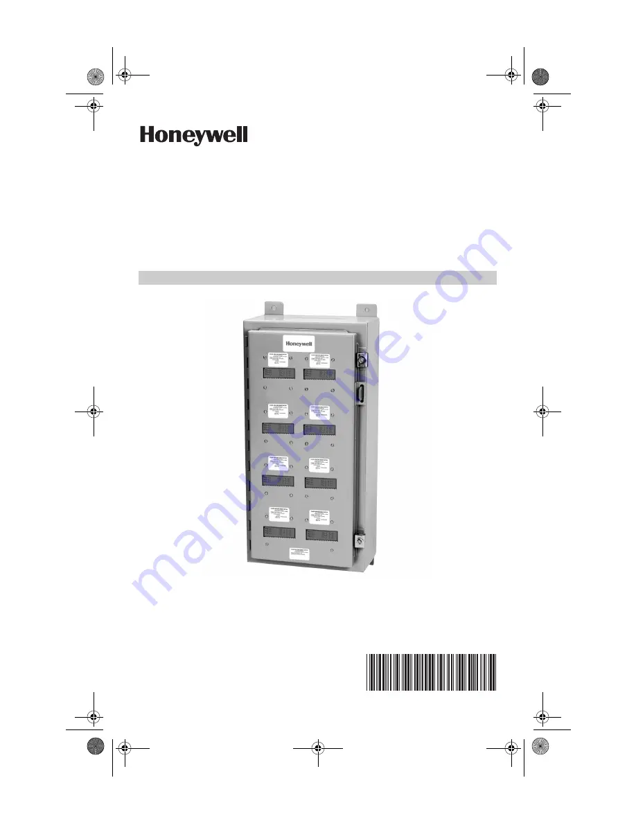
Honeywell E-Mon
®
MMU-Style Meters
KWH AND KWH/DEMAND
715 Peachtree Street NE
Atlanta, GA 30308
customer.honeywell.com
62-0417_B.fm Page 1 Tuesday, May 8, 2018 1:35 PM
Страница 1: ...2 0417 02 OWNER S MANUAL Honeywell E Mon MMU Style Meters KWH AND KWH DEMAND Honeywell E Mon 715 Peachtree Street NE Atlanta GA 30308 customer honeywell com 62 0417_B fm Page 1 Tuesday May 8 2018 1 35 PM ...
Страница 2: ...ur products we provide toll free technical and sales support Monday through Friday 8 00 am to 7 30 pm EST 800 334 3666 You may also reach us via email at info emon com If you have questions we can handle them quickly and effectively with a telephone call Please let us try to help you BEFORE you remove your meter And to help us help you we ask that you have all relevant information on hand when you...
Страница 3: ...binet Wiring 10 Section 6 2 MMU Cabinet Wiring 11 Section 6 3 MMU Cabinet Wiring 11 Section 7 0 Individual Meter Wiring Diagrams and Installation Procedures 12 Section 7 1 Class 1000 2000 and Green Class Meter Wiring Diagrams and Installation Procedures 12 Section 7 2 Class 3200 Meter Wiring Diagrams and Installation Procedures 13 Section 7 3 IDR Interval Data Recorders Wiring Diagrams and Install...
Страница 4: ... label to minimize risk The presence of this label is a cautionary indicator identifying a danger risk The manual should be consulted prior to proceeding The presence of this label indicates an electrical shock hazard exists in the location or area where the label is placed Prior to proceeding the MAINS power must be disconnected and the manual consulted for safety information 62 0417_B fm Page 4 ...
Страница 5: ...or to performing any wiring operations review all contents of the user manual and de energize the MAINS power switch Only qualified personnel should perform installation wiring Installation wiring must comply with all local and national electrical codes CAUTION Failure to ground the enclosure creates a possible shock hazard Do not operate the MMU Style Meter without a protective earth wire attache...
Страница 6: ...ies Voltage and current are continuously measured and updated to provide highly accurate true RMS power information via current sensors 3 2 General Description The MMU allows for compact installation of multiple meters that allows for easy and centralized reading A single MMU cabinet can be configured to contain up to 8 16 or 24 meters of different voltage configurations i e 208V and 480V Fig 1 MM...
Страница 7: ...r the utility meter and store kW and kVAR data for automatic meter reading Refer to Sections 5 6 7 for general installation instructions on installing Class 3200 meters into a MMU Cabinet 4 3 Green Class Meters The Green Class Meter is a power meter for use in sub metering applications The devices take inputs from current sensors and the line voltage and output kW hours in pulses Refer to Sections...
Страница 8: ...nsing for the intended location Use appropriately sized mounting hardware to fasten the MMU enclosure to the selected mounting surface The four housing mounting holes are located on the upper and lower mounting brackets Serviceability field Repair Service and repair should be completed by qualified personnel only Meters cannot be calibrated in the field Adjustment is limited to reset of the meter ...
Страница 9: ...upply entry for the voltage and current sensor conductors The conduit and fittings must be appropriate for the application and installed in a manner to meet national and local electrical codes Spaces not occupied by meters will have a blank metal cover over the display window Fig 3 Example of an 8 Meter MMU Enclosure 62 0417_B fm Page 9 Tuesday May 8 2018 1 35 PM ...
Страница 10: ...4 The letters refer to the three phases and neutral connections already made to the meters The power only has to be landed on the terminal block in order to power all of the meters in the MMU As with the stand alone meters the power wires must be fused The size of the fuse will be determined by the number of meters installed in the MMU The Littelfuse KLDR series are used for this component Each me...
Страница 11: ...uctors c All wiring is to be routed away from any points that may possibly dam age or abrade the insulation such as sharp edges screw threads burrs or any other item that may have been installed in the MMU enclo sure The final wiring must allow the door to freely open and close with out coming in contact with anything that could damage it NOTE Following the proper wiring procedures will help to as...
Страница 12: ...nted on the back panel of the enclosure The wiring terminals are labeled GND HIGH and LOW to correspond to the appropriate connections of the communication cabling Tighten the terminals to 9 in lbs of torque Class 1 rated Belden 1120A cable 600V is to be used for communication wiring in MMU enclosures The communication cabling must be routed away from the mains wiring 62 0417_B fm Page 12 Tuesday ...
Страница 13: ...1000 2000 and Green Class Meter Installation Manuals for detailed wiring diagrams and installation procedures The menu buttons on the Class 1000 MMU 2000 MMU and Green Class MMU Meters are in the same positions as a stand alone Class 1000 2000 or Green Class Meters The MMU Menu Buttons are identified in the figure below If you have any questions contact Honeywell E Mon at 800 334 3666 Fig 6 Class ...
Страница 14: ...at 800 334 3666 NOTE The menu buttons on the Class 3200 MMU Meter are reversed from the stand alone Class 3200 Meters The menu buttons positions are identi fied in the figure below Fig 7 The Menu Buttons on a Class 3200 MMU Meter are Reversed from the Stand Alone Version 7 3 IDR Interval Data Recorders Wiring Diagrams and Installation Procedures Refer to the IDR Installation Manual for detailed wi...
Страница 15: ...TOR IDR TO E MON D MON METERS 1 8 6 COND 22 26 AWG RJ 45 PINS 1 8 NOT USED IDR TO IDR 4 COND 26 AWG RJ 11 IDR TO USB KEY 4 COND 26 AWG RJ 11 USB KEY TO COMPUTER 3 FT USB A to USB B Cable RJ 45 DTE IDR TO PULSE METER 2 COND 14 22 AWG SUPPLIED BY E MON NOTE INTERIOR INTERCONNECTING COMMUNICATIONS ARE SUPPLIED WITH THE PRE WIRED MMU TYPE METERING CABINETS NOTE WHEN CONSTRUCTING FIELD INSTALLED CABLES...
Страница 16: ...WG RJ 45 PINS 1 8 NOT USED IDR TO USB KEY 4 COND 26 AWG RJ 11 IDR TO RS 232 KEY 2000 4 COND 26 AWG RJ 11 RS 232 KEY 2000 TO COMPUTER 8 COND 22 26 AWG RJ 45 DTE FLAT MODULAR CABLE IDR TO PULSE METER 2 COND 14 22 AWG SUPPLIED BY E MON NOTE INTERIOR INTERCONNECTING COMMUNICATIONS ARE SUPPLIED WITH THE PRE WIRED MMU TYPE METERING CABINETS NOTE WHEN CONSTRUCTING FIELD INSTALLED CABLES MODULAR CABLES MU...
Страница 17: ...CHANNEL 1 AC ADAPTER E MON EKM T UP TO 16 METERS CHANNEL 3 RS 232 SERIAL PORT COM1 THROUGH COM4 MAX 15 LOCAL MODEM TELEPHONE LINK UP TO 52 IDRS PER CHANNEL UP TO 52 IDRS PER CHANNEL IDR A IDR A IDR Z UP TO 8 METERS UP TO 8 METERS UP TO 8 METERS IDR 8 USING E MON D MON METERS CHANNEL 2 CHANNEL 1 UP TO 4000 FEET TOTAL AC ADAPTER UP TO 8 METERS CHANNEL 3 E MON EKM T M33483 UP TO 4000 FEET TOTAL UP TO...
Страница 18: ...EL 3 UP TO 4000 FEET TOTAL UP TO 52 IDRS NOTES METERS 1 16 MUST BE INSTALLED WITHIN 500 FEET OF IDR METERS 1 16 USE 6 CONDUCTOR CABLE RS 232 KEY RS 232 SERIAL PORT COM1 COM4 UP TO 8 METERS UP TO 8 METERS IDR 8 USING E MON D MON METERS IDR IDR IDR IDR PC UP TO 4000 FEET TOTAL UP TO 52 IDRS M33484 AC ADAPTER AC ADAPTER AC ADAPTER AC ADAPTER AC ADAPTER 62 0417_B fm Page 18 Tuesday May 8 2018 1 35 PM ...
Страница 19: ...NDUCTOR CABLE AC ADAPTER RS 232 KEY 6 FOOT CABLE PROVIDED BY E MON 15 FEET MAX RS 232 SERIAL PORT COM1 COM4 UP TO 16 METERS UP TO 16 METERS AC ADAPTER IDR IDR IDR IDR IDR IDR IDR IDR M33485 PC UP TO 4000 FEET TOTAL UP TO 4000 FEET TOTAL UP TO 26 IDR 16S PC 6 FOOT CABLE PROVIDED BY E MON 15 FEET MAX RS 232 SERIAL PORT COM1 COM4 RS 232 KEY UP TO 4000 FEET TOTAL UP TO 4000 FEET TOTAL AC ADAPTER AC AD...
Страница 20: ...de years of trouble free service If the meter should not function the following guide will assist in troubleshooting the installation Refer to the individual Meter Installation Manual for detailed troubleshooting information If you have any questions contact Honeywell E Mon at 800 334 3666 BEFORE removing the meter 9 0 METER TECHNICAL SPECIFICATIONS Refer to the individual Meter Installation Manua...
Страница 21: ...s authorization and according to its approved procedures iii the alleged defect is a result of abuse misuse improper maintenance improper installation accident or the negligence of any party iv damaged as a result of events beyond Hon eywell E Mon s control or other force majeure events or v used in conjunc tion with equipment components accessories parts or materials not supplied or approved by H...
Страница 22: ...HONEYWELL E MON MMU STYLE METERS 62 0417 02 22 62 0417_B fm Page 22 Tuesday May 8 2018 1 35 PM ...
Страница 23: ...HONEYWELL E MON MMU STYLE METERS 23 62 0417 02 62 0417_B fm Page 23 Tuesday May 8 2018 1 35 PM ...
Страница 24: ...Technologies In the U S Honeywell 715 Peachtree Street NE Atlanta GA 30308 customer honeywell com U S Registered Trademark 2018 Honeywell International Inc 62 0417 02 M S Rev 05 18 Printed in United States 62 0417_B fm Page 24 Tuesday May 8 2018 1 35 PM ...