background image

WEB-700 WEB-700-O CP-700

25

95-7776—01

WEB-700; WEB-700-O; CP-700

Cleaning

If dust or metal filings are present inside the unit, clean with vacuum or compressed air. Otherwise, no cleaning inside the unit is 

required. If the cover becomes dirty, you can wipe it with a damp cloth and mild detergent.

Required NiMH Battery Maintenance

Battery life expectancy is a function of its discharge cycles (the number of discharges and their depth) and the ambient 

temperature of the battery during normal operation. In most applications, the NiMH battery should see relatively few discharges. 

Therefore, ambient temperature has more to do with the life expectancy of the battery than does any other factor. If the WEB/

CP-700 is installed in a conditioned space, this battery should provide dependable service for approximately three years 

(average). In an environment where the operating temperature is higher (that is, 50ºC or 122ºF), you should only expect the 

battery to last approximately one year.

The NiMH battery in the WEB/CP-700 controller is fully discharged when factory shipped. Additionally, NiMH batteries lose 

charge over time if not kept trickle-charged (for more details, see NiMH battery pack, page 23). Therefore, even a new unit (or 

replacement battery) will require up to 18 hours of powered operation before it can provide reliable backup power (is at full 

charge).

The WEB/CP-700 monitors the NiMH battery and periodically loads the battery to test its ability to maintain battery-backed 

functions. Investigate any battery trouble message, and check the battery connections to the unit. Replace the battery as 

required. To order a new battery, see “Standard Replacement Parts” on page 27. See the section below for a replacement 

procedure.

REPLACING THE NIMH BATTERY

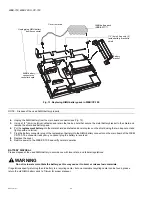
The replacement NiMH battery is an assembly, that is a custom battery pack with an attached cable and connector plug. See 

Fig. 13. To replace the battery, you must remove power to the unit and remove its cover.

CAUTION

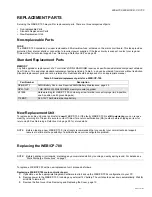
Use only NiMH battery packs approved for use with the WEB/CP-700.

Replacing NiMH battery assembly on a WEB/CP-700.

1. Backup

 the WEB/CP-700 controller’s configuration to your PC using the appropriate NiagaraAX software tool (for exam-

ple, Workbench).

2.

Remove all power from the WEB/CP-700, including any sealed lead-acid battery. Wait for LED activity to stop—after a 

couple of minutes, all LEDs on the unit should be off.

3.

Remove the cover. See Removing and Replacing the Cover, page 10.

At this point you have access to the NiMH battery assembly (Fig. 13).

Содержание CP-700

Страница 1: ...emoving and Replacing the Cover 10 Board Layout 11 About Expansion Options 12 About Option Cards 12 About DDR 2 RAM Upgrade 13 About Remote I O Modules 15 About MiniPCI Cards 15 Wiring Details 15 Communications Wiring 15 Grounding 17 Power Wiring 18 Contact Inputs 20 External 12V Backup Battery 21 Wiring to Remote I O Modules 22 Power Up and Initial Checkout 22 Apply Power 22 Check the Status LED ...

Страница 2: ...s See the section About Expansion Options page 12 Related Documentation For more information on configuring and using the WEB CP 700 controller consult the following documents IO 16 REM H Installation and Configuration Instructions Form 95 7768 NPB LON Option Installation Sheet Form 62 0263 NPB MDM Option Installation Sheet Form 95 7730 NPB GPRS W H Installation Sheet Form 62 0301 Niagara AX Insta...

Страница 3: ...f the WEB CP 700 Fig 1 WEB CP 700 Cover removed with 2 options installed on main board Typical installation requires an NPB PWR UN H universal power supply module furnishing 15Vdc for power attaching to the controller s left side An RS 485 port is on the controller s opposite right end connector along with 15Vdc power for support of remote I O expansion modules either chained directly and or wired...

Страница 4: ...battery pack is included inside the unit and a separate connector provides recharging and monitoring of an external 12V sealed lead acid battery ordered separately The table below provides a summary of features of the WEB CP 700 controller model Table 1 WEB CP 700 features and options Model Description Ports WEB 700 O CP 700 DIN mountable controller PowerPC 440Epx 667MHz processor 1GB NAND Flash s...

Страница 5: ...nd wiring to end connector Includes integral rechargeable NiMH backup battery pack for short duration AC power fail operation Connection for external rechargeable 12V sealed lead acid battery for continuous system operation over longer power outages Provides trickle charge and monitoring support to separately ordered batteries OPERATING SYSTEM QNX Neutrino Real Time Operating System IBM J9 JVM Jav...

Страница 6: ...oller s end connector A multimeter is needed to check polarity DIN rail type NS35 7 5 35mm x 7 5mm and DIN rail end clips stop clips unless using panel mounting method with screws through mounting tabs Suitable tools and fasteners for mounting unit and accessories 2 phillips screwdriver used to install and remove an optional option card Small flat blade screwdriver used for making wiring connectio...

Страница 7: ...n securely grounded object Do not handle printed circuit boards PCBs without proper protection against static discharge Use a wrist strap when handling PCBs The wrist strap clamp must be secured to earth ground Battery Precautions CAUTION The NiMH battery used in this device may present a risk of fire or chemical burn if mistreated Do not disassemble heat above 122ºF 50ºC or incinerate Replace bat...

Страница 8: ... location subject to electrical noise This includes the proximity of large electrical contractors electrical machinery welding equipment spark igniters and variable frequency drives Physical Mounting The following information applies about physically mounting the unit You can mount the WEB CP 700 in any orientation It it not necessary to remove the cover before mounting Mounting on a 35mm wide DIN...

Страница 9: ...ne edge of the DIN rail Fig 3 3 Use a screwdriver to pry down the plastic locking clip and push down and in on the module to force the locking clip to snap over the other edge of the DIN rail 4 Mount the WEB CP 700 controller onto the DIN rail in the same way such that its left 6 position end connector faces the NPB PWR UN H power supply 5 Slide the two devices together along the DIN rail to conne...

Страница 10: ...bon cable connects the cover to the main board Be careful when lifting the cover off If the controller is on a flat work surface you can leave the cable connected with the cover next to the unit See Fig 4 Fig 4 Removing WEB CP 700 cover NOTE If accessory modules are plugged into the WEB CP 700 you may need to slide them away from the unit to get to the end cover tabs To remove the cover press in t...

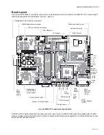
Страница 11: ...ble and RAM can also be upgraded For related details see the next section About Expansion Options P S OUT PS OUT BB 12V RS 485 RS 485 485 GND PS P S NiMH battery connector keyed LEDs for USB hub port activity Dual USB ports Earth grounding lug LED header Serial mode select jumper Option card 2 area including socket header MiniPCI socket DDR 2 RAM Option card 1 area including socket header RS 232 D...

Страница 12: ...cations features with the following available models with others still in development listed in Table 2 1Unlike with a Series 2 6 controller with an NPB MDM installed in slot 1 the onboard RS 232 COM1 port DB9 remains opera tional Also any NPB MDM option is unaffected by the mode jumper position for serial shell access jumper in serial shell position affects the operation of the onboard RS 232 COM...

Страница 13: ...option card must be removed later 4 Carefully insert the pins of the option card into the socket headers of the option card slot NOTE If installing in Slot 2 first carefully pry up the shield tab that goes over the standoff Option card 2 must be installed under the shield tab See Fig 6 page 14 for an exploded view The mounting holes on the option board should line up with the standoffs on the base...

Страница 14: ... into the socket 10 Push down on the back of the SODIMM module until socket end clips snap in place Ensure the module is installed cor rectly Only a small even area of its gold edge connectors should be visible where they enter the socket 11 Reinsert any option card removed from slot 1 being careful to align pins correctly such that mounting holes align with the standoffs If no option card was ins...

Страница 15: ...13 for a procedure For complete details refer to the specific documentation that accompanied the option 2 Connect communications cables See Communications Wiring page 15 for ports available on the WEB CP 700 base unit For ports on any installed option board RS 232 LON RS 485 modem see the specific mounting and wiring guide for any additional details 3 Apply power to the unit See Power Up and Initi...

Страница 16: ...h has a UART capable of operation up to 115 200 baud At the bottom of the board see Fig 7 page 16 is an RS 232 port using an DB 9 plug male connector On the right side of the unit is an isolated RS 485 port using the bottom three terminals of a 6 position screw terminal connector plug NOTE Additional serial ports may be added with option card s in Option Slot 1 and Slot 2 such as an NPB RS232 card...

Страница 17: ...th USB ports are low current ports capable of supplying up to 100 mA at 5V maximum A typical application for a USB port is to use with a USB Flash drive for the transfer of files The QNX OS running on the WEB CP 700 can automatically recognize an inserted Flash drive as a physical disk Grounding An earth ground spade lug 0 187 is provided on the controller for connection to earth ground For maximu...

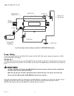
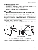
Страница 18: ...NPB PWR UN H Disconnect power to this circuit before installation to prevent electrical shock of equipment damage Make all connections in accordance with national and local electrical codes Use copper conductors only Do not exceed the 30W capacity of NPB PWR UN H by the powered devices Power input connections are made to the terminals on the NPB PWR UN H circuit board cover removal is required Use...

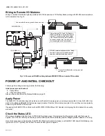
Страница 19: ... Power and ground is also provided in wiring to remote I O modules through the 6 position connector However note for each remote I O module you should also connect its earth ground spade lug to earth ground at that module s location NPB WPM US WALL MOUNT AC ADAPTER You can order and adapt a wall mount AC adapter model NPB WPM US to power only the WEB CP 700 controller To use the adapter you must c...

Страница 20: ...itor normally closed N C alarm contacts if available on a UPS and or the door tamper switch of an enclosure These CIs are unsupervised no end of line resistors are required Fig 10 shows example wiring to all three CIs of the WEB CP 700 Fig 10 Contact Input wiring to WEB CP 700 B B UP S A C UP S B A T T G ND G ND G ND DOOR T MP B B WEB CP 700 Tamper switch UPS Alarm Contacts Power Fail if available...

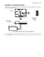
Страница 21: ...bout the Backup Batteries page 23 Fig 11 Sealed lead acid backup battery connection on WEB CP 700 NOTE The minimum wire size for battery connections is 18AWG 1 0mm2 for up to 4 ft 1 22m or 16AWG 1 29mm2 for up to 12 ft 3 66m UP S AC UP S B A T T G ND G ND G ND DOOR T MP B T B T PS PS B B R S 485 WEB CP 700 712BNP 12V Sealed Lead Acid Backup Battery ies 15Vdc power and backup battery passed through...

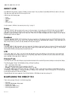
Страница 22: ...r with a NPB WPM US Wall Mount AC Adapter simply plug the AC adapter into a nearby wall outlet Check the Status LED When power is applied the front cover STATUS LED will light green This indicates that the system is OK and that power is applied The STATUS LED may be blinking until the QNX OS has finished loading and the Niagara platform daemon is running Once this boot sequence has finished the ST...

Страница 23: ...upon loss of primary power the controller performs an immediate shutdown backing up data and powering off including attached readers and expansion modules A NiMH battery characteristic is to lose charge if not left in charge mode trickle charge Leaving the battery uncon nected or the unit powered off will cause the battery to fully discharge in a matter of weeks Note that in the case of a new cont...

Страница 24: ...he WEB CP 700 has been rebooted with the serial mode select jumper in the serial shell position see Fig 5 page 11 This indicates that the DB 9 RS 232 port is operating in serial shell mode USB Three yellow LEDs LD1 LD2 and LD3 are located together on the upper left area on the main board in the option slot 2 area These LEDs indicate USB hub and port 1 and 2 activity respectively These LEDs will no...

Страница 25: ...details see NiMH battery pack page 23 Therefore even a new unit or replacement battery will require up to 18 hours of powered operation before it can provide reliable backup power is at full charge The WEB CP 700 monitors the NiMH battery and periodically loads the battery to test its ability to maintain battery backed functions Investigate any battery trouble message and check the battery connect...

Страница 26: ...H battery connector on the main board of the WEB CP 700 The connector is keyed you cannot plug the battery in reversed 8 Replace the cover 9 Restore power to the WEB CP 700 and verify normal operation BATTERY DISPOSAL Please dispose of the used NiMH battery in accordance with local state and federal regulations WARNING Do not incinerate or mutilate the battery as this may cause it to burst or rele...

Страница 27: ...ridium Be sure to contact Tridium for a return authorization RA number before shipping an item for return credit See Returning a Defective Unit page 28 for more details NOTE Before ordering a new WEB CP 700 it is strongly recommended that you contact your normal technical support resource to eliminate the possibility of a software issue or mis configuration problem Replacing the WEB CP 700 NOTE Be...

Страница 28: ...store power to the unit It should boot up as a new unit see Check the Status LED page 22 14 Using the NiagaraAX platform tools re commission the WEB CP 700 and install the saved station database For more details see the NiagaraAX Install and Startup Guide Returning a Defective Unit For proper credit on an in warranty unit ship the defective unit to Tridium within 30 days NOTE If the defective unit...

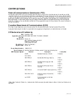
Страница 29: ...nadian Interference Causing Equipment Regulations Cet appareil numerique de la classe A respecte toutes les exigencies du Reglement sur le material broilleur du Canada CE Declaration of Conformity I Steve Fey President of Tridium Inc hereby declare that the equipment specified above conforms to the above Directives and Standards Date December 2009 Application of Council Directive 89 336 EEC 92 31 ...

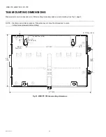
Страница 30: ...ting is recommended over tab mounting See Fig 3 page 9 NOTE Electronic and printed versions of this guide may not show the dimensions to scale Verify all measurements before drilling Fig 14 WEB CP 700 tab mounting dimensions 0 1590 Dia 4 04 0 98 24 9 0 334 Dia 8 5 0 35 8 9 5 0 127 1 72 43 7 0 170 Dia 4 32 8 7 221 5 6 142 2 50 63 5 ...

Страница 31: ...0 WEB 700 O CP 700 31 95 7776 01 WEB 700 WEB 700 O CP 700 Fig 15 WEB CP 700 with power supply attached NPB PWR UN H 8 125 206 3 48 88 55 2 50 63 5 Distance between center of tabs from one unit to another unit ...

Страница 32: ...ell International Inc 1985 Douglas Drive North Golden Valley MN 55422 Honeywell Limited Honeywell Limitée 35 Dynamic Drive Toronto Ontario M1V 4Z9 customer honeywell com U S Registered Trademark 2010 Honeywell International Inc 95 7776 01 M S 03 10 Printed in U S A ...

Отзывы: