background image

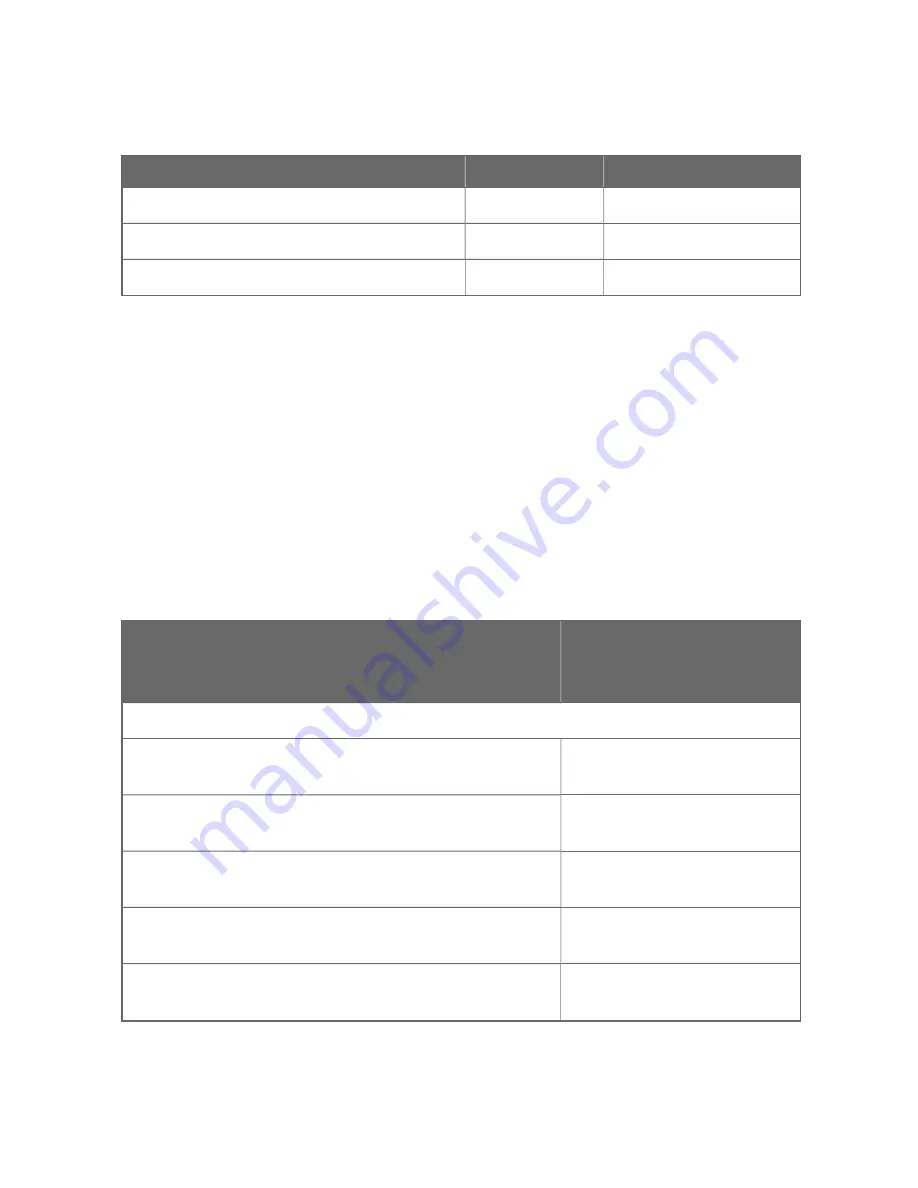
Wire Type

Power input

RS485 Connector

Solid Wire (MAX)

12 AWG

12 AWG

Stranded Wire (MAX)

14 AWG

14 AWG

With plastic collar ferrule (MAX)

1.5 mm²

1.5 mm²

Table 4-5: Wire Conductor Size Range for Ports and Connectors

Communication Cabling

Ethernet cables

Ethernet cables are used in Series C cabinets to interconnect Control
Firewall IOTAs, CN100 Controller IOTAs, and Series C Modules. Only
shielded twisted pair (STP) type cable is used. The use of unshielded
twisted pair (UTP) cable is not allowed.

Other in-cabinet Ethernet cable parts

One of the following yellow-colored (FTEA) cables and one of the
following green-colored (FTEB) Ethernet cables are used to connect a
Control Firewall IOTA to a CN100 Controller IOTA or to a Series C
Modules.

Description

Model or

Part
Number

FTE Link A Cables

FTEA Ethernet Cable, STP CAT5,
Yellow, 24 inches (610 mm) long

51305980-
124

FTEA Ethernet Cable, STP CAT5,
Yellow, 36 inches (1 m) long

51305980-
136

FTEA Ethernet Cable, STP CAT5,
Yellow, 48 inches (1.2 m) long

51305980-
148

FTEA Ethernet Cable, STP CAT5,
Yellow, 60 inches (1.5 m) long

51305980-
160

FTEA Ethernet Cable, STP CAT5,
Yellow, 84 inches (2 m) long

51305980-
184

30

Chapter 4 - CN100 Platform Installation

Содержание CN100

Страница 1: ...CN100 Controller Hardware Planning and Installation Guide EPDOC X630 en 516A August 2020 EXPERION PKS RELEASE 516 ...

Страница 2: ...al Sàrl While this information is presented in good faith and believed to be accurate Honeywell disclaims the implied warranties of merchantability and fitness for a purpose and makes no express warranties except as may be stated in its written agreement with and for its customer In no event is Honeywell liable to anyone for any direct special or consequential damages The information and specifica...

Страница 3: ...Installation Declarations 19 Dimensions and Layouts 20 Dimensions of Redundant CN100 Controller 21 Installation Dimensions for a Redundant Controller 23 Mounting 24 Mounting a Controller on dinrail 24 Mounting a Controller on CCA 24 Wiring and Cabling Planning 26 Power Cabling 27 Grounding and Other Considerations 28 Communication Cabling 30 Connecting with Wireless I O 33 Chapter 5 Maintenance 35...

Страница 4: ... 48 Chapter 7 Special Condition of Use and Approved Standards 51 Approval Rating of CN100 51 Special Condition of Use for Division 2 Zone 2 Hazardous Location Installation 52 For the United States 52 For Canada 52 For ATEX and IECEx 53 Approved Standards for Division 2 Zone 2 Hazardous Location 53 US Approval Standards 53 Canadian Standards 54 European Standards Zone 2 54 CE LVD and EMC Compliance...

Страница 5: ... of document Introduction to Experion Technology Item Description CN100 Module CN100 controllers running the eCLR IEC 61131 3 execution environment with CN100 software options configured with Control Builder Network Adapter Module NAM Network Adaptor Modules CC INAM01 provides for Uplink Ethernet connections and supports copper or Fiber connectivity Special terms The following table describes some...

Страница 6: ... page 9 for more information Plan the wiring of your system See Wiring and Cabling Planning on page 26 for more information Troubleshoot your system Diagnostics and Troubleshooting on page 1 Remove or replace system components See Maintenance on page 35 for more information Software installation See Software Installation User s Guide for detailed information Software configuration See Control Buil...

Страница 7: ... with valid credentials If the equipment is not used in a manner not specified by the manufacturer the protection provided by the equipment may be impaired CN100 controller is a modular powerful and scalable system capable of all remote automation and control applications When combined with Experion PKS and its simplified SCADA configuration it solves the remote automation requirements Starting wi...

Страница 8: ...8 Chapter 2 Overview ...

Страница 9: ...be expanded with the same CN100 Platform I O Modules or connect with Series C IOM by IOLINK Depending on software support other form factor I O modules along with Wireless I O are supported See the images and table below for the CN100 Platform Hardware Figure 3 1 Redundant CN100 Controller CCA Front View 9 ...

Страница 10: ...le 3 1 CN100 Hardware Components Item Model Number Description 1 CC IION01 I O NETWORKING CONTROL MODULE 2 CC TION11 I O NETWORKING CONTROL IOTA 3 CC TION13 I O NETWORKING CONTROL IOTA DIN RAIL 4 CC INAM01 NETWORK ADAPTER MODULE 10 Chapter 3 Hardware Components ...

Страница 11: ...11 Item Model Number Description 5 50154761 SPF Single mode 20Km 6 50154762 SPF Multi mode 2Km Chapter 3 Hardware Components ...

Страница 12: ...cess controller A CN100 module plugs onto an IOTA designed for the CN100 n Input Output Termination Assembly IOTA An IOTA holds CN100 module NAM and connection for IO link and RS485 The IOTA contains only passive devices and connectors n Network Adapter Module NAM A NAM provides one Ethernet port wired or fibre for the modules FTE connection n The IOTA supports two NAMS 12 Chapter 3 Hardware Compo...

Страница 13: ...13 Figure 3 3 Redundant Controller CCA Figure 3 4 Redundant Controller DINRAIL Chapter 3 Hardware Components ...

Страница 14: ... VDC power supply two 2 RS485 Ports one 3 IO Link Port one 4 Ethernet Ports on the NAM 2 Fiber ports on the NAM 2 5 Screw hole used for locking controller IOTA Table 3 2 CN100 Controller Parts 14 Chapter 3 Hardware Components ...

Страница 15: ... ms Execution cycle time 20 ms Time Synchronization Time synchronization is Network Time Protocol NTP or Precision Time Protocol PTP SD card support 32GB Class 6 Class 10 industry standard not hot swappable maximum weight 3g 0 0066 lb 0 1058 oz ATTENTION Explosion hazard Do not remove the SD card when the Experion system is powered unless the area is non hazardous ATTENTION Risque d explosion Ne p...

Страница 16: ...16 Chapter 3 Hardware Components ...

Страница 17: ...FORM INSTALLATION In this section Environmental Specifications 18 Power Considerations 18 Installation Declarations 19 Dimensions and Layouts 20 Mounting 24 Wiring and Cabling Planning 26 Connecting with Wireless I O 33 17 ...

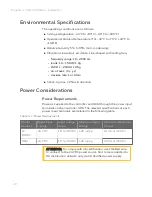
Страница 18: ...r Requirements Power is supplied to the controller and NAM through the power input terminals on the controller IOTA The relevant specifications at each power input terminals are detailed in the following table Model Number Rated input voltage Input voltage range Maximum ripple voltage Maximum rated input current CC IION01 24 VDC 18 to 30 VDC 120 mVpp 0 13 A at 30 VDC NAM 24 VDC 18 to 30 VDC 120 mV...

Страница 19: ...Installation Declarations ATTENTION This equipment shall be installed in accordance with the requirements of the National Electrical Code NEC ANSI NFPA 70 the Canadian Electrical Code CEC or EN IEC60079 14 and applicable National regulations in Europe See Special Condition of Use for Division 2 Zone 2 Hazardous Location Installation on page 52 for more information The suitability of the enclosure ...

Страница 20: ...t in its static shielding box or bag until they are ready for installation ATTENTION Unless the location is known to be non hazardous do not l Connect or disconnect cables l Install or remove components While the control system is powered ATTENTION A moins que vous soyez dans une zone d atmosphère non explosive ne pas l Connecter or déconnecter les câbles l Installer or retirer des composants du s...

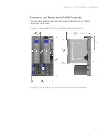
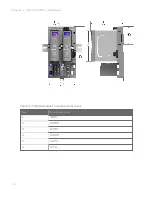
Страница 21: ...ller The following picture illustrates the physical dimensions of CN100 redundant controllers Figure 4 1 Redundant CN100 Controller Dimensions CCA Figure 4 2 Redundant CN100 Controller Dimensions DINRAIL Chapter 4 CN100 Platform Installation ...

Страница 22: ...Item Dimension mm 1 36 85 2 168 88 3 183 97 4 132 08 5 140 51 6 77 54 Table 4 3 The Redundant Controller Dimensions 22 Chapter 4 CN100 Platform Installation ...

Страница 23: ...re illustrates the layout when one redundant controller is connected with one right end plate Figure 4 3 The Dimensions for a Redundant Controller Item Dimension mm inch 1 30 1 2 2 30 1 2 3 50 2 0 4 50 2 0 Table 4 4 The Layout Dimension Chapter 4 CN100 Platform Installation ...

Страница 24: ...A with two screws located at each side of the metal cover 5 Insert the NAM onto IOTA making sure that the NAM matches properly with the IOTA connector 6 Secure the NAMs to the IOTA with clockwise rotary button lock at right side of the module 7 Secure the IOTA to the DIN rail with DIN rail stops Mounting a Controller on CCA When the redundant controller is used perform the following steps to mount...

Страница 25: ... 2 Phillips Screwdriver by hand turn each screw after it is engaged with the thread for three complete clockwise turns in cross pattern sequence 7 Refer to the preceding figure l Insert and tighten the screw to the left side of the IOTA board that connects to the 24 Vdc bus bar l Insert and tighten the screw to the right side of the IOTA board that connects to the COM bus bar 8 Tighten the mountin...

Страница 26: ...Wiring and Cabling Planning In this section Power Cabling 27 Grounding and Other Considerations 28 Communication Cabling 30 26 Chapter 4 CN100 Platform Installation ...

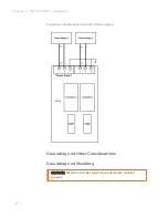
Страница 27: ...of 18 to 30 VDC Power supply for Redundant Controller The CN100 IOTA supports redundant power supply For each power supply connect positive and negative poles of the 24V power source to the power input terminals of the redundant controller This powers the controller and any I O modules connected in the same row as the controller This does not provide the loop power to the field instruments Chapter...

Страница 28: ...gure 4 4 Redundant Controller Power supply Grounding and Other Considerations Grounding and Shielding CAUTION CN100 controller must be connected to chassis ground 28 Chapter 4 CN100 Platform Installation ...

Страница 29: ...fidelity pulse distortion for longer cable lengths is not compromised n Use cables that have a braided shield 55 or greater coverage for best EMI RFI performance Double shielded cable with a braid over foil performs best if the environment is EMI harsh Proper grounding of the shields is necessary to obtain the optimum performance n The shields screen of the cable carrying the pulse signals can be ...

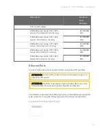
Страница 30: ...d Other in cabinet Ethernet cable parts One of the following yellow colored FTEA cables and one of the following green colored FTEB Ethernet cables are used to connect a Control Firewall IOTA to a CN100 Controller IOTA or to a Series C Modules Description Model or Part Number FTE Link A Cables FTEA Ethernet Cable STP CAT5 Yellow 24 inches 610 mm long 51305980 124 FTEA Ethernet Cable STP CAT5 Yello...

Страница 31: ...hernet Cable STP CAT5 Green 84 inches 2 m long 51305980 284 Ethernet Ports Connect Ethernet ports A and B to their respective FTE switches ATTENTION Confirm the location to be non hazardous prior to adjusting the switch ATTENTION Veuillez vous assurer que vous êtes dans une zone d atmosphère non explosive avant d ajuster le sélecteur The CN100 controller has 2 Ethernet ports on the NAM and use RJ4...

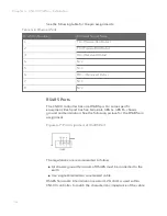
Страница 32: ... Each port has five terminals 485 A 485 B chassis ground and termination See the following picture for the RS485 pin assignment Figure 4 7 Pin Assignment of RS485 Port The regulations are recommended to follow n All chassis ground terminals of RS485 must be connected to the earth n Use single shielded two wire twisted cable RS485 Terminals A termination resistor 120 ohm is used within CN100 contro...

Страница 33: ...ace with either I O Link speed You cannot mix I O of different speeds on the same link Connecting with Wireless I O To connect Wireless I O a Honeywell Field Device Access Point FDAP is connected to the controller through Ethernet A Honeywell FDAP can connect with non redundant controller directly while to connect with a redundant controller a switch is needed ATTENTION Confirm the location to be ...

Страница 34: ...n For detailed and complete information about the Wireless Device Management refer to the Wireless DeviceManager User s Guide 34 Chapter 4 CN100 Platform Installation ...

Страница 35: ...n this section CN100 module NAM IOTA 36 Safety considerations PLAN AHEAD 36 Removal and Insertion Under Power RIUP 37 Replacing a CN100 Controller 37 Replacing a NAM 38 Replacing an IOTA 39 Spare parts and model numbers 41 35 ...

Страница 36: ...ersonnel While there is always an inclination to preserve the materials and time invested in a running process no action should ever be taken that would risk injury to personnel Protection of personnel property is an important consideration that always requires comprehensive knowledge of the entire control process the control equipment the process control strategy and the conditions and circumstan...

Страница 37: ... controlling a process Experion System That is while the system is powered any of the controllers or expansion I O can be removed or inserted l With no physical damage to the controller to the expansion I O or to the other modules in the system l Without disturbing the functions of the controllers or expansion I O in the system Under carefully controlled circumstances this feature enables the user...

Страница 38: ...ancy synchronization state by monitoring the status LED of the secondary controller CN100 Replacing a NAM To replace a NAM 1 If the IOTA is installed on a carrier in a cabinet rotate the rotary button to unlock the NAM holding the NAM to the IOTA and remove the module from the IOTA so power is removed from the connector on the IOTA It is not necessary to completely remove the long gray plastic scr...

Страница 39: ...sert the terminal strips onto the IOTA 11 Completely insert the DIN rail hook to attach the IOTA to the DIN rail 12 Insert the NAM or IOM onto IOTA making sure that the NAM or IOM matches properly with the IOTA connector 13 Secure the NAM or IOM to the IOTA with two screws located at each side of the plastic cover 14 Set the rotary switches to match the IOTA being removed To replace an IOTA on CCA...

Страница 40: ... way to attach the IOTA board to the channel Do not tighten 10 Tighten the six mounting screws securing the IOTA board to the channel a Insert and tighten the screw to the left side of the IOTA board that connects to the 24 Vdc bus bar b Insert and tighten the screw to the right side of the IOTA board that connects to the COM bus bar 11 Set the Device Index address to the same address as the old I...

Страница 41: ...or 16 Secure the controller module to the IOTA board with two screws located at each side of the module 17 Insert the NAM onto IOTA board making sure that the controller circuit board mates properly with the IOTA board connector 18 Secure the NAM to the IOTA board with rotary button located at right side of the module 19 Connect RJ45 or Ethernet link cables to the RJ 45 connectors on NAM Spare par...

Страница 42: ...42 Chapter 5 Maintenance ...

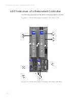
Страница 43: ...sonnel to react appropriately when external actions are required The following diagnostic indicators are provided for the CN100 Controller n Light Emitting Diodes LEDs that assist with troubleshooting activities solely at the controller LEDs are also useful for verifying indications viewed as screen items LED indicators are provided for the following hardware components l Redundant Controller indi...

Страница 44: ... Controller The following figure shows the LEDs in the redundant Controller Figure 6 1 CN100 Redundant Controller LED States CCA Figure 6 2 CN100 Redundant Controller LED States DINRAIL 44 Chapter 6 Diagnostics and Troubleshooting ...

Страница 45: ...45 The various LED states are detailed in the following table Chapter 6 Diagnostics and Troubleshooting ...

Страница 46: ...dition LED Status Color Note ETH1 ETH1 FTEA link is Good Green Bi color LED ETH1 FTEA link is Down FTE A cable disconnected Red Table 6 1 The Controller LED States 46 Chapter 6 Diagnostics and Troubleshooting ...
Страница 47: ...Solid Green Tri color LED CN100 is running in primary or non redundant role soft failure conditions exists Blinking Green CN100 is running in secondary role Solid Orange CN100 is running in secondary role soft failure conditions exists Blinking Orange CN100 is powering up Solid Red CN100 is starting up or is running recovery firmware Blinking Red CTRL CEE is enabled and active RUN Green Tri color ...

Страница 48: ...s many relevant details about the problem n When an CN100 controller failure occurs you should gather information about the controller and the conditions under which it failed This information will be beneficial to Honeywell TAC to help in diagnosing and correcting the fault and or replacing the CN100 controller hardware Performing the following will help you to gather more information about a fai...

Страница 49: ...s operating Additional information which will help the support team to assist you better n Any other status or fail indications on the controller s faceplate observed at the time of the failure or following the event n Detailed summary of the sequence of events leading up to the failure n Operations that preceded the event such as load activate change parameter delete power cycle synchronization s...

Страница 50: ...50 Chapter 6 Diagnostics and Troubleshooting ...
Страница 51: ...Division 2 Group A B C D T4 Ex ec IIC T4 Gc Class I Zone 2 AEx ec IIC T4 Gc AEx nA IIC T4 Gc ATEX II 3 G Ex ec IIC T4 Gc IECEx Ex ec IIC T4 Gc ATTENTION Classification of maximum surface temperatures for Group II electrical equipment are Temperature class Maximum surface temperature T1 450 T2 300 T3 200 T4 135 T5 100 T6 85 51 ...

Страница 52: ...on of UL 60079 0 and UL 60079 7 unless the equipment is afforded an equivalent degree of protection by location For Canada n The installer shall provide transient over voltage protection external to the apparatus such that the voltage at the supply terminal of the apparatus does not exceed 140 of the voltage rating of the equipment n The installation shall provide a controlled environment that lim...

Страница 53: ...otection not less than IP54 in accordance with the test of enclosure section of EN IEC 60079 0 and EN IEC 60079 7 unless the equipment is afforded an equivalent degree of protection by location Approved Standards for Division 2 Zone 2 Hazardous Location Experion meets the following approvals standards US Approval Standards Item Number Nonincendive electrical equipment for use in Class I and II Div...

Страница 54: ... Part 0 Equipment General requirements CAN CSA C22 2 No 60079 0 15 Explosive atmospheres Part 7 Equipment protection by increased safety e CAN CSA C22 2 No 60079 7 16 General Requirements Canadian Electrical Code Part II CSA Std C22 2 No 0 10 R2015 European Standards Zone 2 ATEX Standards Title Number Electrical apparatus for explosive gas atmospheres Part 0 General Requirements EN 60079 0 2018 Ex...

Страница 55: ...c compatibility EMC Part 3 3 Limits Limitation of voltage changes voltage fluctuations and flicker in public low voltage supply systems for equipment with rated current 16 A per phase and not subject to conditional connection IEC 61000 3 3 Electromagnetic compatibility EMC Part 4 2 Testing and measurement techniques Electrostatic discharge immunity test IEC 61000 4 2 Electromagnetic compatibility ...

Страница 56: ...nity test IEC 61000 4 8 Electromagnetic compatibility EMC Part 4 11 Testing and measurement techniques Voltage dips short interruptions and voltage variations immunity tests IEC 61000 4 11 IEC Standards Zone 2 IEC Standards Title Number Electrical apparatus for explosive gas atmospheres Part 0 General Requirements IEC 60079 0 2017 Explosive atmospheres Part 7 Equipment protection by increased safe...

Страница 57: ...licenses notices restrictions and obligations imposed by the licensor The licenses notices restrictions and obligations if any may be found in the materials accompanying the product in the documents or files accompanying such third party materials in a file named third_party_ licenses on the media containing the product or at http www honeywell com ps thirdpartylicenses Documentation feedback You ...

Страница 58: ...against any Honeywell product please follow the instructions at https www honeywell com en us product security Support For support contact your local Honeywell Process Solutions Customer Contact Center CCC To find your local CCC visit the website https www honeywellprocess com en US contact us customer support contacts Pages default aspx Training classes Honeywell holds technical training classes ...

Отзывы: