background image

AQUATROL ZONE SYNCHRONIZING BOILER RESET CONTROLS

3

69-1979—04

LCD Display Panel Layout

The LCD on the AQ251 Control Panel is used to:

— Monitor system status and performance.

— Select and/or modify control settings for the hydronic 

system.

— Diagnose and troubleshoot system problems.

The layout of the display is logical and simple to navigate. The 

information displays so that you can see at a glance the 

system’s operating temperatures, as well as the status of the 

system equipment, such as a call for heat, DHW pump ON, 

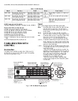
Boiler T-T terminals energized, etc. Fig. 1 on page 2 illustrates 

the layout and features of the LCD display panel and keypad.

LCD Display Navigation

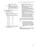
This section describes how the keypad is used to navigate the 

LCD display and menus.
• The LCD displays up to three lines of text at a time. For 

menus with more than three lines, use the up and down 

buttons

 (

or v) to scroll through the menu options.

• As the menu is scrolled up or down, the indicator arrow


(←)


shows which menu item is active.

• If the active menu item is part of a list of predefined options 

(e.g., Day of the Week) press the 

 or + button to scroll 

through the available options until the preferred option is 

displayed. The option is automatically saved when the 

indicator arrow is scrolled away from the value being 

edited. 

• If the active menu item requires you to define a value (e.g., 

a setpoint), use the 

 or + button to decrease or increase 

the value until the desired value is displayed. The selection 

will be saved when the indicator arrow is scrolled up or 

down.

NOTES:

1.

When setting times for the setback schedule, you 

must use the 

 or + button to change the time.

2.

The OK button, when pressed, defaults the time 

setting to “--:--” (midnight).

• If the active menu item leads to a further sub-menu, 

pressing the OK button displays the sub-menu options on 

the LCD. Scroll through this sub-menu to position the 

indicator arrow 

(←)

 beside the desired menu item to input 

or modify. Choose one of the options provided or input the 

desired value for the menu item. When satisfied, scroll to 

another item and your selection will be saved.

• To define or modify another item within the same menu, 

scroll the up and down buttons

 (

or v) until the indicator 

arrow 

(←)

 is beside the desired option. Use the 

 or + 

buttons to set the value for that item.

• To move back (up) one level within a menu, press the 

Menu button. 

• To return to the Home Page display, press the Home 

button. 

NOTE: The AQ251 automatically returns to the Home Page 

display after 60 minutes of inactivity on the keypad.

HOME PAGE DISPLAY

The Home Page is the default view displayed on the AQ251 

Control Panel's LCD screen. 

There are two Home Page views - Simple and Detail.

• Simple view shows 3 lines of text and is a brief description 

of the system operation. 

• Detail view includes the same 3 lines plus 10 lines of 

additional information. Detail view is the factory default.

The choice of the Simple or Detail Home Page view is made 

from the USER MENU > PREFERENCES/TIME menu option.

The Home Page display information for the Simple and Detail 

views is illustrated in Fig. 2.

Fig. 2. Home Page displays (Simple and Detail).

M27749

WEDNESDAY    9:30A

PROGRAM:     LEAVE  

 RETRN SLEEP WAKE OCC UNOCC

OUTDOOR:        -5    

TARGET:        180  

 WWSD -


-

BOILER:        180

RETURN:        160

DHW:           100

ZONE COUNT:     31

WEDNESDAY    9:30A

PROGRAM:     LEAVE

OUTDOOR:        -5            

Menu

Home

KEYPAD

HOME PAGE (SIMPLE)

HOME PAGE (DETAIL)

LCD DISPLAY

Содержание AQ251

Страница 1: ... experienced licensed service technicians should service this Control Panel The front cover of the AQ251 Control Panel should not be removed as this will expose the user to potentially dangerous line voltage 120V electricity Congratulations The AQUATROL AQ251 installed on your heating system is the most powerful yet user friendly hydronic heating control system available on the market for resident...

Страница 2: ...umber the displayed value will decrease increase by pressing these buttons When holding the or button for more than a second the values automatically decrease increase at a faster pace similar to setting the time on a digital clock radio If the menu item is an option pressing these buttons scrolls through the list of available options one at a time Fig 1 LCD Dot Matrix Display Layout Model Functio...

Страница 3: ...tback schedule you must use the or button to change the time 2 The OK button when pressed defaults the time setting to midnight If the active menu item leads to a further sub menu pressing the OK button displays the sub menu options on the LCD Scroll through this sub menu to position the indicator arrow beside the desired menu item to input or modify Choose one of the options provided or input the...

Страница 4: ...for both the AQ251 control s LCD and the zone thermostats The time display in 12 hour e g 7 00 PM or 24 hour format e g 19 00 Date and time of day allows building owner to reset day and time of day in the event of a power outage of more than 4 hours refer to Troubleshooting section The Home Page display view Simple or Detail The factory default is Detail The LCD Backlight illuminated permanently O...

Страница 5: ...ur programs have been set select the COPY TO ALL DAYS option This displays the prompt COPY TO ALL DAYS ARE YOU SURE Select Yes by positioning the indicator arrow at YES and press the OK button Next the same list of days as EDIT DAILY described in step 1 displays except that all days now show the times for the WAKE LEAVE RETRN and SLEEP programs that you set in the EDIT ALL DAYS menu If you do not ...

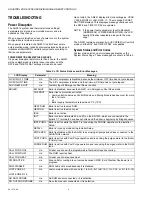
Страница 6: ...ve and the minimum ON time has not yet elapsed AUX IN EM SHUT n a Auxiliary Input s Emergency Shut Down is active BOILER EM SHUT Boiler is disabled because the AQ251 is in Emergency Shut Down mode FRZ PROT Boiler freeze protection activated Communication between Control Module and Zoning Module has been lost for more than 1 minute or Boiler supply temperature is less than 50 F 10 C HEAT DHW Boiler...

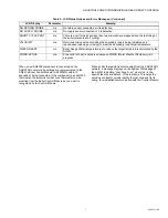
Страница 7: ...ntractor quickly identify the lost zone and fix its wiring to re establish communication with the Control Module NO RETURN PROBE n a No return sensor connected or it is defective NO SUPPLY PROBE n a No supply sensor connected or it is defective SHORT CYCLE PROT n a There is a call for heat but less than two minutes have elapsed since the last firing of the boiler prevents short cycling VALVE INIT ...

Страница 8: ...CLE PROT VALVE INIT WATER READY WWSD ACTIVE SYSTEM STATUS 1 ZONE A 1 ROOM TEMP FLOOR TEMP SETPOINT 70 FLOOR SETPT 70 HEAT COOL STATUS SETBACK 7 SETPOINT MAX 100 SETPOINT MIN 41 FLOOR LIM HI 100 FLOOR LIM LO 41 SETPOINT VACANCY HEAT 41 SETPOINT VACANCY COOL 100 CHANGEOVER 2 KEYBOARD UNLOCK ZONE SETTINGS All or Single 2 ARE YOU SURE NO YES MON WAKE 6 00A MON LEAVE 8 00A MON RETRN 4 30P MON SLEEP 10 ...

Отзывы: