Revision: 1.1
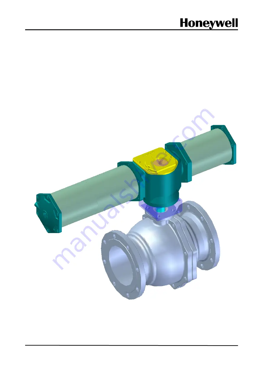
Series 9410
Ball Valve
70-16-45-06-EN
INSTALLATION, OPERATION, MAINTENANCE MANUAL
Страница 1: ...Revision 1 1 Series 9410 Ball Valve 70 16 45 06 EN INSTALLATION OPERATION MAINTENANCE MANUAL ...
Страница 2: ...ections before Operation 7 5 Maintenance and Repair 8 5 1 General 9 5 2 Body Disassembly and Assembly See Fig 5 1 9 5 2 1 Disassembly 9 5 2 2 Assembly 10 6 Preventive Maintenance and Troubleshooting 11 6 1 Troubleshooting 11 7 Others 12 7 1 Procedure for Switching Action Reverse Action Direct Action 12 ...
Страница 3: ...ave professional assembly capabilities are required to maintain Ball valves Therefore it is more economical to request repairs of the valves to Honeywell As the valves repaired by Honeywell are thoroughly tested and warranted you are recommended to entrust Honeywell with repairs 2 Storage A Do not throw drop trip or drag ball valves when transporting them B Keep all parts of the ball valve in a we...
Страница 4: ...ts are processed with rust preventive oil before shipping to prevent corrosion remove the rust preventive oil from the pipes before installing them on the line C Blow off all foreign substances including welding chips in the pipes before starting installation D Install valves in the direction of arrow marked on the body CAUTIONS When moving control valves you should handle them carefully so that t...
Страница 5: ...al parts in a balanced manner sequentially in diagonal direction See Fig 3 1 Fig 3 1 Procedure for Fastening Flange Bolts F Install the valve at right angle to the ground as much as possible If this is impossible attach a support to the valve before installing it See Fig 3 2 and 3 3 Fig 3 2 Installing Support Fig 3 3 Installation Location of Actuator 1 6 4 8 2 5 3 7 ...
Страница 6: ... See Fig 3 4 In addition a space for manual operation is required if a manual hand wheel has been installed Fig 3 4 Space required for control valve installation A Face to Face Dimension B Minimum distance from obstacles Approx 30 cm C Space for removing the actuator Approx 40 cm ...
Страница 7: ...ature to control flow by opening the bypass valve Moreover it is ideal to choose the same flow characteristics and size as those of control valve Fig 3 6 shows an example of ideal control valve installation recommended by Honeywell Fig 3 6 Example of Control Valve Installation Recommended by Honeywell Block Valves Pressure gauges 응축수 회수관 6 Steam trap Drain Valve 6 Bypass Valve Control Valve 3 5 1 ...
Страница 8: ...or vibration by turbulent flow the straight pipe length at the valve exit must be at least 3 to 5 times the pipe diameter Straight piping at the entrance and exit allows the preservation of accurate operation status by enabling accurate measurement of the pressure at the entrance and exit See Fig 3 7 Fig 3 7 Minimum straight pipe length for valve performance and pressure measurement 배관구경 x 13 배관구경...
Страница 9: ...pressure required for valve operation is accurately set Cylinder Actuator 5 0kgf cm2 Specified in the name plate Electrical devices such as limit switch or solenoid valve are attached to an control valve Even if the manufacturer has adjusted them the tubing may be bent or the valve stem s position becomes incorrect due to a shock during transportation or careless handling during assembly Therefore...
Страница 10: ... life span of the valve can increase if you replace parts according to their replacement cycles Refer to the Part Replacement Cycle Sheet shown below Part Replacement Cycle Sheet Item Name Replacement Cycle Others Packing 2 years Gasket 2 years Ball 2 years Replace after inspection according to the fluid conditions and used environment Seat 2 years Replace after inspection according to the fluid c...
Страница 11: ...asket 31 from the body 1 and the body cap 2 Clean each part and check them for any damage Prepare available parts for future repair WARNING To prevent human injuries and damages to control system close the block valve remove instrument air and signals from the valve and open the bypass valve to switch over the pressure from the line to the bypass Then slowly unfasten the bolts from the pipe until ...
Страница 12: ...gasket and gland packing RECOMMENDATIONS Be sure to inspect and replace worn out parts before reassembling them You are recommended to replace soft products such as packing gasket and seat always before reassembling 5 2 2 Assembly Assemble in the reverse sequence of the disassembly Fig 5 1 Body Assembly Diagram ...
Страница 13: ...all safety precautions at the site 3 Disassemble the valve Visually inspect the stem Check whether the plug components are damaged and replace them if necessary Also replace the gland packing Excessive internal leak when the valve is blocked Seat 1 Check the air pressure supplied to the valve 2 If you suspect any damage to ball or seat go to item 3 3 Disassemble the valve Visually check ball and s...
Страница 14: ... air operated valve 3 Disassemble the valve and check whether there are any foreign substances in the ball and seat 4 Check the design temperature and actual line temperature 5 Remove the actuator and try to operate the actuator only The valve does not respond to input signals 1 Check the air pressure supplied to the valve 2 Check the voltage of the solenoid valve 3 Apply the correct air pressure ...
Страница 15: ...ocess Solutions TAC hfs tac support honeywell com Australia Honeywell Limited Phone 61 7 3846 1255 FAX 61 7 3840 6481 Toll Free 1300 36 39 36 Toll Free Fax 1300 36 04 70 China PRC Shanghai Honeywell China Inc Phone 86 21 5257 4568 Fax 86 21 6237 2826 Singapore Honeywell Pte Ltd Phone 65 6580 3278 Fax 65 6445 3033 South Korea Honeywell Korea Co Ltd Phone 822 799 6114 Fax 822 792 9015 ...
Страница 16: ...es Visit www honeywellprocess com Or contact your Honeywell Account Manager Process Solutions Honeywell 1250 W Sam Houston Pkwy S Houston TX 77042 Honeywell Control Systems Ltd Honeywell House Skimped Hill Lane Bracknell England RG12 1EB Shanghai City Center 100 Jungi Road Shanghai China 20061 www honeywellprocess com Honeywell ...