21
Mounting and Connection Instructions Blocking Element 3
5.
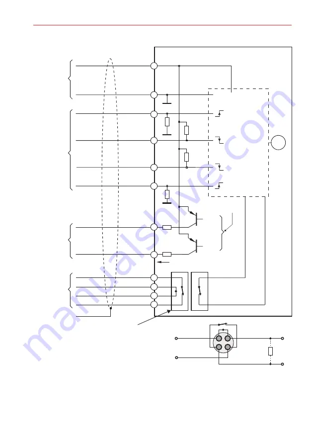
Connection diagram
Connection of magnetic contact in Z-wiring:
It is not of importance which pair of cores is used as input or output.
To connect the contact, measure the short-circuited connection.
The end of line resistor R must always be attached to the final device of a detector group.
The outputs for the end position message (brown and grey) are "open collector" outputs with a
standard resistor of 10
. (high active, I_max = 50 mA)
A
W
+12 V DC
+U_b
0 V
0 V
M
+
+
I_max=50 mA
10R
10R
+
+
R
A
Close
Open
Close
Closed
Open
Open
Outputs
Operating
voltage
Inputs (Function see Cap
. 4)
Magnetic contact
red
blue
black
yellow
pink
green
brown
grey
white
Shield
previous contact or
central control unit
Input
Output
next contact or
end of line resistor
internal
magnetic contact
Closed
Open
Bolt end position
Actuation
Blocking element 3
white
white
white
external m
for
opening
agnetic contact
monitoring of


