- 2-
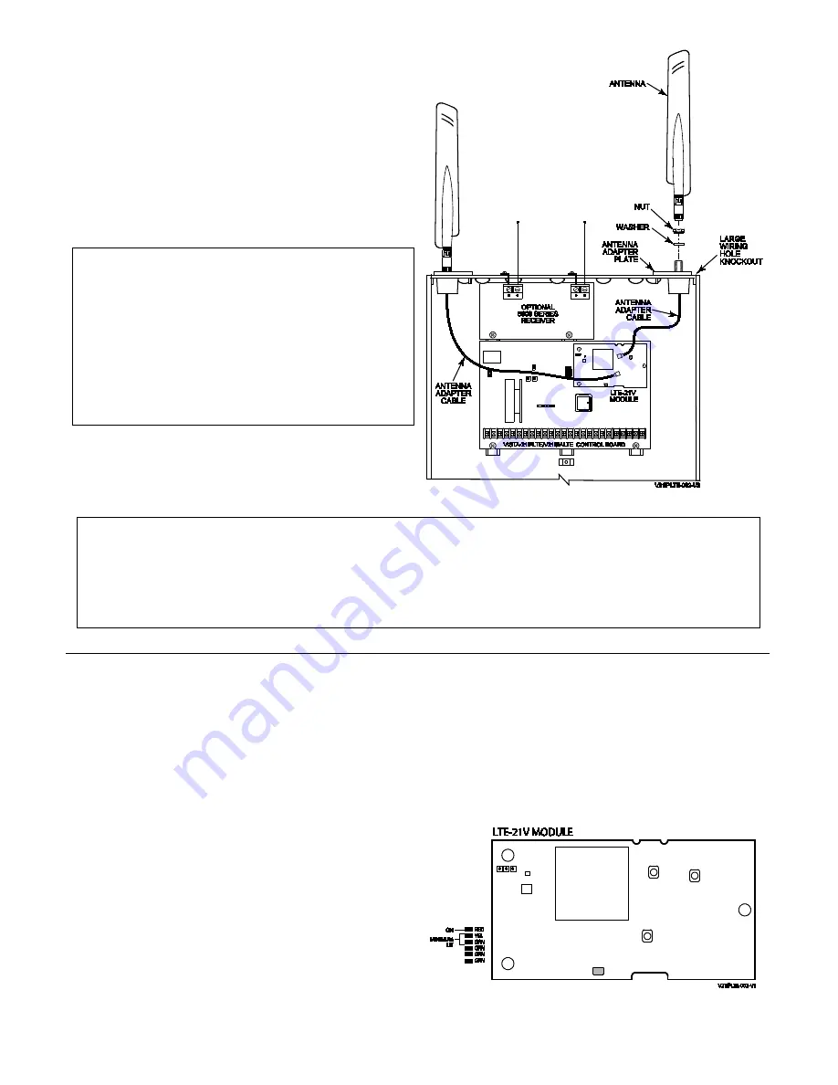
2. Install the Antenna Adapter Plates.
a. Punch out the large wiring-hole knockout and the
adjacent smaller knockout from the cabinet’s upper-
right and left topside.
b. Position the antenna adapter plate over the large
knockout, aligning the plate’s pin with the smaller
knockout and push until the adapter snaps into place.
c. Remove the nut and washer from the antenna adapter
cable then secure the cable’s SMA connector to the
adapter plate with the washer and nut as shown.
3. Install the Antennas.
RF Exposure
Warning
– The antenna(s) used for this transmitter must be
installed to provide a separation distance of at least 7.8 inches (20
cm) from all persons and must not be co-located or operating in
conjunction with any other antenna or transmitter except in
accordance with FCC multi-transmitter product procedures.
Mise en Garde
Exposition aux Frequences Radio:
La/les antenne(s) utilisée(s)
pour cet émetteur doit/doivent être installée(s) à une distance de
séparation d'au moins 20 cm (7,8 pouces) de toute personne et ne
pas être située(s) ni fonctionner parallèlement à tout autre
transmetteur ou antenne, excepté en conformité avec les
procédures de produit multi transmetteur FCC et ISEDs
The antennas mount directly onto the antenna adapter cable
at the antenna adapter plate.
Carefully align the antenna’s connector over the SMA
connector protruding from the adapter plate, then screw it
down (clockwise) until it is finger tight. Do not over tighten.
*
LTE-21V Initial Power Up
: Upon initial power up, the communicator LEDs blink in repeated sequence from top to
bottom indicating network initialization.
Green (REG)
Yellow (TX/RX)
Red (FAULT)
This sequence may take up to 15 minutes.
Do not reset power during this time.
When initialization is complete, the Signal Quality display LEDs will light and the yellow and red LEDs may blink (per their
respective functions).
After initial network setup, subsequent resets or power ups can take up to 90 seconds.
Checking Signal Quality
The Signal Quality / Mode and Status LEDs normally display
the module’s signal quality. LED 1 (red LED on the top) will
be lit to indicate that the display is in signal quality mode, and
the other LEDs indicate signal strength (lowest to highest,
from left to right) between the module and the receiving
tower.
•
This allows you to immediately determine if the
desired mounting location has sufficient signal
strength for proper operation.
•
For proper operation, look for at least 3 bars lit solid.
NOTE:
The module must be registered to transmit messages
to AlarmNet and your central station.
The following are tips for maximizing signal quality:
•
The best signal quality can usually be found on an
exterior wall at the highest point in the building.
Avoid the basement.
•
Maintain at least 12 inches clearance between
antenna and steel I-beams, HVAC ducts, metal
studs, steel roofs, exterior walls with metalized
insulation or aluminum siding and other large metal
objects.
If a consistent two bars cannot be found, the control cabinet
may have to be moved to an area of better reception.


