10
| English
The perimeter wire can be buried up to 5 cm under the
ground (or non-metallic slabs) .
To avoid causing damage to the perimeter wire, do not
verticut or rake the area where it is positioned .
When laying out the wire avoid angles of less than 45° .
This can affect the performance .
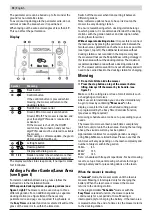
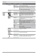
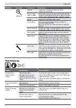
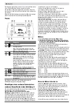
Display
Symbol
Meaning
Back button
Confirm button
If the confirm button is pressed whilst
mowing, the mower will return to the
docking station
Red LED on: mower error
Green LED on: mower is switched on
Green LED off: The mower is inactive and
your four-digit PIN code is required for
activation .
Or the mower is shut off, the On/Off
switch must be turned on and your four
digit PIN code must be entered to activate
the mower .
Note: during a software update, the green
LED and red LED will be on .
Left/right button
Down/up button
Display with dialog screen
1 2 3
Garden number (shown when more than
one garden map in the mower memory)
The display switches into sleep mode, if no input is made
for 10 minutes .
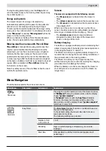
Adding a Further Garden/Lawn Area
(see figure I)
To install an additional lawn area, please follow the
instructions in the Installation Guide .
With separate docking station, separate gardens (see
figure I, right):
The mower can be used on up to three
different gardens . For an additional garden, a separate
docking station (see figure
A
) and the necessary
perimeter wire and pegs are required . If a schedule or
the
Easy Timer
calendar function is selected it will cut the
grass of the area it is in, within the time slots .
Switch off the mower when transporting it between
different gardens .
Note: software updates have to be carried out on the
mower in every docking station .
To ensure remembering which docking station belongs
to which garden, it is recommended to label the docking
stations with the garden number and description when
storing them for winter .
Without separate docking station:
It is possible to connect
the lawn areas by placing the perimeter wire between the
two lawn areas parallel to each other as close as possible
(see figure I, top left) . The additional lawn area without
docking station is not recorded in the map memory and
the mower will not use the Map & Mow cutting strategy in
this lawn area without the docking station . The maximum
recommended lawn area without a docking station is 40
m
2
. The mower will mow until it runs out of battery and will
need to be carried back to the docking station for charging .
Mowing
f
Do not let children ride the mower.
f
Press the stop button on top of the mower before
lifting. Always lift the mower by its handle. (see
figure F).
Make sure the cutting area is free of small animals such
as hedgehogs or tortoises .
After successful installation you can either immediately
be-gin to mow by confirming
"Mow now"
on the
display, or wait for the next scheduled cutting period,
as programmed by the Easy Timer Calendar Function
(previous setting required) .
A mowing schedule can also be set up according to your
needs .
The mower must mow a lawn area 3 times completely
(do 3 full cuts) to learn the lawn area . During the learning
phase, the visual result may not be optimal .
Approximate runtimes for complete garden coverage
using Map & Mow are listed below . Please note that the
run times will vary depending on the lawn complexity and
number of objects within the garden .
100 m
2
4 h
350 m
2
12 h
400 m
2
14 h
Set a schedule with frequent repetitions . For best mowing
results, set up a frequent mowing schedule for longer
lasting battery and for preventing debris on the lawn .
When the mower is mowing
In
"manual"
mode, the mower works until the lawn is
mowed . Mowing is interrupted only for charging the
battery . When the lawn area is mowed, the mower
returns to the docking station .
In the programmable
"Schedule"
mode or with the
Easy Timer
calendar function, the mower operates
continuously for a set period of time . Mowing is
interrupted only for charging the battery . If the lawn area
is mowed before the end of a time slot, the mower returns
to the docking station .
Содержание Miimo HRM40
Страница 1: ...MIIMO HRM40 ORIGINAL INSTRUCTIONS ...
Страница 3: ...2 ...
Страница 109: ...108 C 2 m 5 m 125 m 180 x B ...
Страница 110: ... 109 1cm 3 0 c m 3 cm 3 cm 3 cm 3 cm E D ...
Страница 111: ...110 MAX 50 mm 40 mm MIN 30 mm MAX 50 mm MIN 30 mm STOP G F Mi im o HR M4 0 ...
Страница 112: ... 111 H I ...
Страница 113: ...112 STOP STOP K J ...
Страница 114: ...EN PP xx xxxx xx Printed in Europe 3RY0E600 00X3R Y0E 6000 Honda Motor Europe Ltd 2019 ...

