


9-6
CYLINDER HEAD/VALVES
GX120K1•GX160K1•GX200
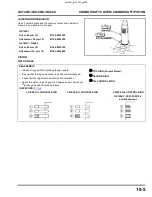
VALVE GUIDE REPLACEMENT
1.Chill the replacement valve guides in the freezer for about an
hour.
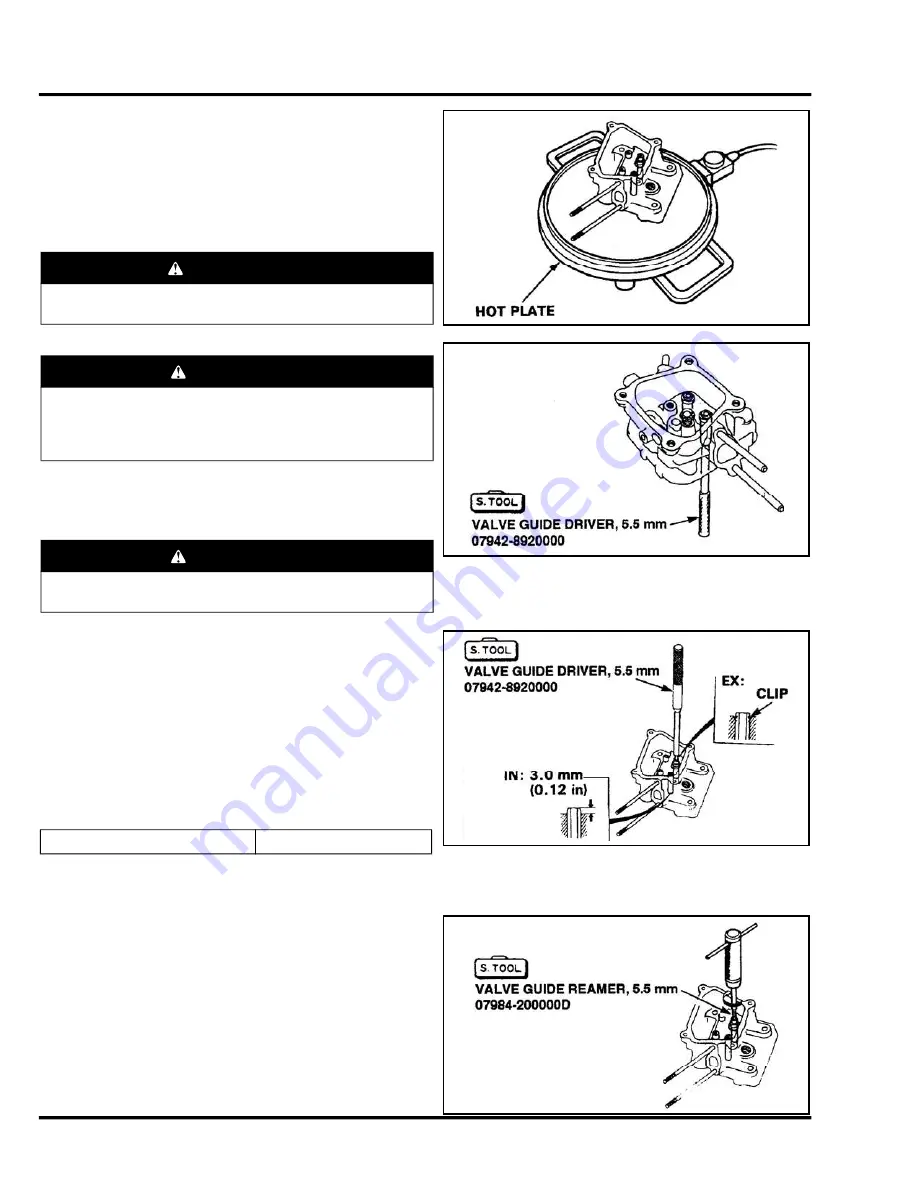
2.Use a hot plate or oven to heat the cylinder head evenly to
150° C (300° F).
Check the temperature with a temperature indicating stick
(available at welding supply stores) or equivalent.
3.Remove the heated cylinder head from the hot plate and
support it with wooden blocks. Drive the valve guides out of
the head from the combustion chamber side.
4.Remove the new valve guides from the freezer one at a time
as needed.
5.Install the new valve guides from the valve spring side of the
cylinder head.
Exhaust side: Drive the exhaust valve guide until the clip is
fully seated as shown.
Intake side: Drive the intake valve guide to the specified height
(measured from the top of the valve guide to the cylinder
casting as shown).
6.After installation, inspect the valve guide for damage.
Replace the guide if damaged.
VALVE GUIDE REAMING
Note:
For best results, be sure the cylinder head is at room
temperature before reaming valve guides.
1.Coat the reamer and valve guide with cutting oil.
2.Rotate the reamer clockwise through the valve guide the full
length of the reamer.
3.Continue to rotate the reamer clockwise while removing it from
the valve guide.
WARNING
• To avoid burns, use heavy gloves when handling the
heated cylinder head.
CAUTION
• Do not use a torch to heat the cylinder head; warpage of
the cylinder head may result.
• Do not get the head hotter than 150° C (300° F); excessive
heat may loosen the valve seats.
CAUTION
• When driving the valve guides out, be careful not to
damage the head.
IN valve guide installation height
3.0 mm (0.12 in)
gx120k1_gx160k1_gx200
Содержание GX120K1
Страница 13: ...1 8 SPECIFICATIONS GX120K1 GX160K1 GX200 3 PERFORMANCE CURVES GX120K1 GX120U1 GX120UT1 gx120k1_gx160k1_gx200 ...
Страница 14: ...1 9 GX120K1 GX160K1 GX200 SPECIFICATIONS GX160K1 GX160U1 GX160UT1 gx120k1_gx160k1_gx200 ...
Страница 15: ...1 10 SPECIFICATIONS GX120K1 GX160K1 GX200 GX200 GX200U GX200UT gx120k1_gx160k1_gx200 ...
Страница 16: ...1 11 GX120K1 GX160K1 GX200 SPECIFICATIONS 4 DIMENSIONAL DRAWINGS GX120K1 Unit mm in gx120k1_gx160k1_gx200 ...
Страница 18: ...1 13 GX120K1 GX160K1 GX200 SPECIFICATIONS GX120K1 RAMMER TYPE Unit mm in gx120k1_gx160k1_gx200 ...
Страница 19: ...1 14 SPECIFICATIONS GX120K1 GX160K1 GX200 GX160K1 Unit mm in gx120k1_gx160k1_gx200 ...
Страница 67: ...4 4 AIR CLEANER MUFFLER GX120K1 GX160K1 GX200 Rammer type P 3 6 P 3 6 gx120k1_gx160k1_gx200 ...
Страница 68: ...4 5 GX120K1 GX160K1 GX200 AIR CLEANER MUFFLER 2 MUFFLER DISASSEMBLY REASSEMBLY P 3 11 gx120k1_gx160k1_gx200 ...
Страница 69: ...4 6 AIR CLEANER MUFFLER GX120K1 GX160K1 GX200 Rammer type gx120k1_gx160k1_gx200 ...
Страница 71: ...5 2 RECOIL STARTER FAN COVER GX120K1 GX160K1 GX200 GX200 gx120k1_gx160k1_gx200 ...
Страница 80: ...6 1 6 CARBURETOR 1 CARBURETOR 6 2 gx120k1_gx160k1_gx200 ...
Страница 81: ...6 2 CARBURETOR GX120K1 GX160K1 GX200 1 CARBURETOR REMOVAL INSTALLATION gx120k1_gx160k1_gx200 ...
Страница 82: ...6 3 GX120K1 GX160K1 GX200 CARBURETOR Rammer type gx120k1_gx160k1_gx200 ...
Страница 101: ...9 1 9 CYLINDER HEAD VALVES 1 CYLINDER HEAD VALVES 9 2 gx120k1_gx160k1_gx200 ...
Страница 109: ...10 1 10 CRANKSHAFT COVER CRANKSHAFT PISTON 1 CRANKCASE COVER CRANKSHAFT PISTON 10 2 gx120k1_gx160k1_gx200 ...
Страница 111: ...10 3 GX120K1 GX160K1 GX200 CRANKSHAFT COVER CRANKSHAFT PISTON RAMMER TYPE 8 x 32 6 GX160K1 GX200 gx120k1_gx160k1_gx200 ...
Страница 120: ...11 1 11 GOVERNOR OIL LEVEL SWITCH 1 GOVERNOR OIL LEVEL SWITCH 11 2 gx120k1_gx160k1_gx200 ...
Страница 124: ...12 2 REDUCTION UNIT GX120K1 GX160K1 GX200 1 L TYPE REDUCTION DISASSEMBLY REASSEMBLY gx120k1_gx160k1_gx200 ...
Страница 126: ...12 4 REDUCTION UNIT GX120K1 GX160K1 GX200 3 CAMSHAFT P T O 1 2 REDUCTION N TYPE gx120k1_gx160k1_gx200 ...
Страница 128: ...12 6 REDUCTION UNIT GX120K1 GX160K1 GX200 5 RAMMER TYPE 6005 BALL BEARING gx120k1_gx160k1_gx200 ...