background image

7-4

dummyhead

dummyhead

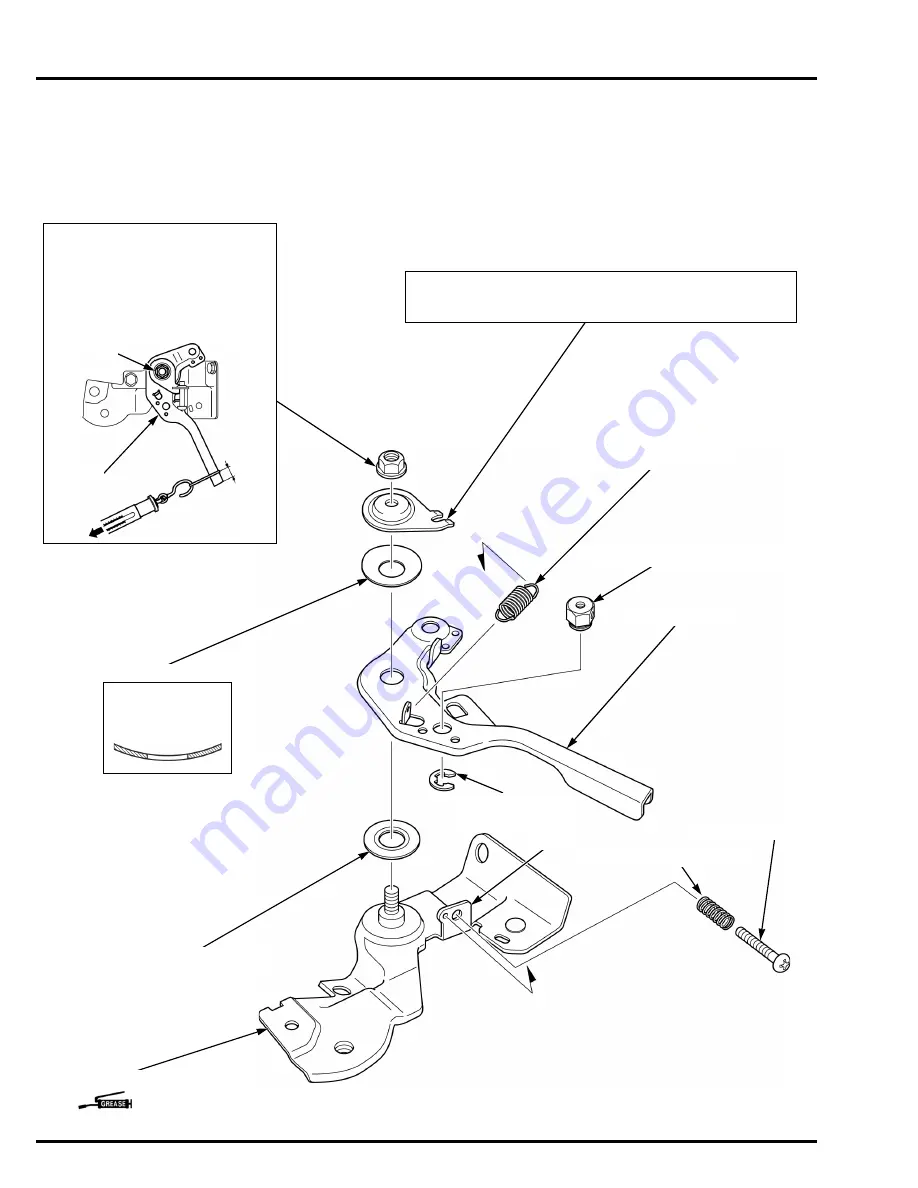
GOVERNOR SYSTEM

CONTROL BASE 

DISASSEMBLY/ASSEMBLY

REMOTE TYPE

Remove the control base (page 7-3).

INSTALLATION:
After installation the control base Assy., 
measure force at 10 mm (0.4 in) from 
the tip of the control lever [1] by pulling. 
Adjust by turning the lock nut [2] so that 
the gauge shows 19.6 ± 4.9 N (2.0 ± 
0.5 kgf) when the control lever starts to 
move.

CONTROL LEVER WASHER

CONTROL LEVER

CONTROL BASE

CONTROL LEVER SPACER

CLAW

LOCK NUT (6 mm)

INSTALLATION:
Install the control lever washer by aligning the cutout of the control 
lever washer with the claw of the control base.

CABLE RETURN SPRING

INSTALLATION:
Note the installation 
direction.

(Control lever sliding surface)

LEVER SPRING

[1]

[2]

10 mm 
(0.4 in)

SCREW (5 x 25 mm)

CONTROL ADJUST SPRING

WIRE HOLDER (Except QX3 type)

CIRCLIP
(Except QX3 type)

Содержание GP160H

Страница 1: ...ring appropriate clothing and using safety equipment When performing any service task be especially careful of the following Read all of the instructions before you begin and make sure you have the tools the replacement or repair parts and the skills required to perform the tasks safely and completely Protect your eyes by using proper safety glasses goggles or face shields anytime you hammer drill...

Страница 2: ...CIFICATIONS 1 SERVICE INFORMATION 2 MAINTENANCE 3 TROUBLESHOOTING 4 FAN COVER 5 FUEL SYSTEM 6 GOVERNOR SYSTEM 7 IGNITION SYSTEM 8 STARTING SYSTEM 9 OTHER ELECTRICAL 10 MUFFLER 11 CYLINDER HEAD 12 CRANKCASE 13 WIRING DIAGRAMS 14 INDEX ...

Страница 3: ...is not practical or possible to warn you about all the hazards associated with servicing these products You must use your own good judgement Honda Motor Co Ltd SERVICE PUBLICATION OFFICE Date of Issue July 2014 You will find important safety information in a variety of forms including Safety Labels on the product Safety Messages preceded by a safety alert symbol and one of three signal words DANGE...

Страница 4: ...he hole Use only metric tools when servicing this unit Metric bolts nuts and screws are not interchangeable with non metric fasteners The use of incorrect tools and fasteners will damage the unit SYMBOLS The symbols used throughout this manual show specific service procedures If supplementary information is required pertaining to these symbols it will be explained specifically in the text without ...

Страница 5: ...ne Coolant Temperature ECM Engine Control Module EMT Exhaust Manifold Temperature EOP Engine Oil Pressure EX Exhaust F Front or Forward GND Ground HO2S Heated Oxygen sensor IAB Intake Air Bypass IAC Idle Air Control IAT Intake Air Temperature I D Inside diameter IG or IGN Ignition IN Intake INJ Injection L Left MAP Manifold Absolute Pressure MIL Malfunction Indicator Lamp O D Outside Diameter OP O...

Страница 6: ... 1 SPECIFICATIONS SERIAL NUMBER LOCATION 1 2 P T O TYPE VARIATION 1 2 DIMENSIONS AND WEIGHTS SPECIFICATIONS 1 3 ENGINE SPECIFICATIONS 1 4 PERFORMANCE CURVES 1 6 DIMENSIONAL DRAWINGS 1 8 P T O DIMENSIONAL DRAWINGS 1 10 ...

Страница 7: ...rankcase Refer to them when ordering parts or making technical inquiries P T O TYPE VARIATION GP160H GP200H 2 3 1 P T O type Q V Type QHB1 QHKR QMPB QX3 VX3 Control base Remote Internal EXP Fixed throttle operation Oil alert unit P T O type Q V Type QHB1 QHKR QMPB QX3 VX3 Control base Remote Internal EXP Fixed throttle operation Oil alert unit ...

Страница 8: ...63 mm 14 3 in Overall height Q 335 mm 13 2 in V 335 mm 13 2 in Dry weight Q 14 9 kg 32 8 lbs V 14 9 kg 32 8 lbs Operating weight Q 17 8 kg 39 2 lbs V 17 8 kg 39 2 lbs P T O type DIMENSIONS AND WEIGHTS Overall length Q 323 mm 12 7 in V 333 mm 13 1 in Overall width Q 378 mm 14 9 in V 378 mm 14 9 in Overall height Q 335 mm 13 2 in V 335 mm 13 2 in Dry weight Q 16 0 kg 35 0 lbs V 16 0 kg 35 0 lbs Oper...

Страница 9: ...2 68 x 1 77 in Net power SAE J1349 1 3 6 kW 4 8 HP 3 600 min 1 rpm Continuous rated power 2 9 kW 3 9 HP 3 600 min 1 rpm Maximum net torque SAE J1349 1 10 3 N m 1 05 kgf m 7 6 lbf ft 2 500 min 1 rpm Compression ratio 8 5 1 Fuel consumption at continuous rated power 1 1 4 Liters 0 37 US gal 0 31 Imp gal h Ignition system Transistorized magneto Ignition timing B T D C 25 1 400 min 1 rpm Recommended s...

Страница 10: ... in Net power SAE J1349 1 4 1 kW 5 5 HP 3 600 min 1 rpm Continuous rated power 3 7 kW 5 0 HP 3 600 min 1 rpm Maximum net torque SAE J1349 1 12 4 N m 1 26 kgf m 9 1 lbf ft 2 500 min 1 rpm Compression ratio 8 5 1 Fuel consumption at continuous rated power 1 1 7 Liters 0 45 US gal 0 37 Imp gal h Ignition system Transistorized magneto Ignition timing B T D C 20 1 400 min 1 rpm Recommended spark plug B...

Страница 11: ...ATIONS PERFORMANCE CURVES GP160H lbf ft kgf m N m kW 2 1 0 3 TORQUE OUTPUT HP PS 0 9 4 3 2 1 0 3 2 1 0 NET POWER NET TORQUE RECOMMENDED OPERATING SPEED RANGE 2 000 3 000 3 600 P T O SPEED min 1 rpm 5 4 5 4 11 10 9 8 0 7 5 7 0 1 0 1 1 ...

Страница 12: ...FICATIONS GP200H lbf ft kgf m N m kW 2 1 0 3 TORQUE OUTPUT HP PS 1 1 4 3 2 1 0 3 2 1 0 NET POWER NET TORQUE RECOMMENDED OPERATING SPEED RANGE 2 000 3 000 3 600 P T O SPEED min 1 rpm 5 4 5 4 13 12 11 9 0 8 5 8 0 1 2 1 3 10 5 6 6 9 5 ...

Страница 13: ...ad SPECIFICATIONS DIMENSIONAL DRAWINGS P T O type page 1 2 GP160H Unit mm in 239 9 4 106 4 2 162 6 4 96 3 8 39 5 1 56 75 5 2 97 Q type 314 12 4 V type 324 12 8 93 3 7 334 13 1 124 4 9 363 14 3 5 0 2 80 3 1 157 6 2 335 13 2 ...

Страница 14: ... 9 dummyhead dummyhead SPECIFICATIONS GP200H Unit mm in 254 10 0 106 4 2 162 6 4 96 3 8 39 5 1 56 75 5 2 97 Q type 323 12 7 V type 333 13 1 106 4 2 336 13 2 124 4 9 378 14 9 5 0 2 80 3 1 157 6 2 335 13 2 ...

Страница 15: ...T O type page 1 2 GP160H Q type Unit mm in 65 1 2 56 88 3 46 5 16 24UNF 2B 4 PLACES CRANKSHAFT P T O 65 1 2 56 30 1 18 5 16 24UNF 2B Unit mm in 61 4 2 42 58 5 2 30 17 0 0 67 Φ 19 025 19 050 0 7490 0 7500 16 260 16 360 0 6402 0 6441 4 730 4 780 0 1862 0 1882 5 16 24UNF 2B ...

Страница 16: ...1 11 dummyhead dummyhead SPECIFICATIONS V type Φ 19 830 19 843 0 7807 0 7812 71 4 2 81 Unit mm in 5 16 24UNF 2B TAPER 2 1 4 33 5 1 32 Φ 18 927 19 177 0 7452 0 7550 ...

Страница 17: ... Q type Unit mm in 65 1 2 56 88 3 46 5 16 24UNF 2B 4 PLACES CRANKSHAFT P T O 65 1 2 56 30 1 18 5 16 24UNF 2B Unit mm in 61 4 2 42 58 5 2 30 17 0 0 67 Φ 19 025 19 050 0 7490 0 7500 16 260 16 360 0 6402 0 6441 4 730 4 780 0 1862 0 1882 5 16 24UNF 2B ...

Страница 18: ...1 13 dummyhead dummyhead SPECIFICATIONS V type Φ 19 830 19 843 0 7807 0 7812 71 4 2 81 Unit mm in 5 16 24UNF 2B TAPER 2 1 4 33 5 1 32 Φ 18 927 19 177 0 7452 0 7550 ...

Страница 19: ...MEMO dummyhead dummyhead ...

Страница 20: ...2 1 2 dummytext 2 SERVICE INFORMATION MAINTENANCE STANDARDS 2 2 TORQUE VALUES 2 4 LUBRICATION SEAL POINTS 2 5 TOOLS 2 6 HARNESS AND TUBE ROUTING 2 8 ...

Страница 21: ... 711 Big end side clearance 0 30 0 70 0 012 0 018 1 1 0 04 Big end I D 30 015 30 025 1 1817 1 1821 30 066 1 1837 Big end oil clearance 0 035 0 055 0 0014 0 0022 0 12 0 005 Crankshaft Crankpin O D 29 970 29 980 1 1799 1 1803 29 92 1 178 Crankshaft runout 0 10 0 004 Cylinder barrel Camshaft journal I D 14 000 14 018 0 5512 0 5519 14 048 0 5531 Crankcase cover Camshaft journal I D 14 000 14 027 0 551...

Страница 22: ...0 30 0 70 0 012 0 018 1 1 0 04 Big end I D 30 015 30 025 1 1817 1 1821 30 066 1 1837 Big end oil clearance 0 035 0 055 0 0014 0 0022 0 12 0 005 Crankshaft Crankpin O D 29 970 29 980 1 1799 1 1803 29 92 1 178 Crankshaft runout 0 10 0 004 Cylinder barrel Camshaft journal I D 14 000 14 018 0 5512 0 5519 14 048 0 5531 Crankcase cover Camshaft journal I D 14 000 14 027 0 5512 0 5522 14 048 0 5531 Valve...

Страница 23: ...25 Special 18 1 8 13 Oil level switch joint nut M10 x 1 25 10 1 0 7 Flywheel nut M14 x 1 5 Special nut 75 7 5 55 Apply engine oil to the threads and seating surface Fuel tank nut bolt M6 x 1 0 10 1 0 7 Fuel tank joint M10 x 1 25 2 0 2 1 5 Air cleaner mount nut M6 x 1 0 9 0 9 6 6 Muffler nut M8 x 1 25 24 2 4 18 Muffler stay bolt GP200H only M6 x 1 0 12 1 2 9 Recoil starter set screw M6 x 1 0 Specia...

Страница 24: ...cker arm pivot threads and pivot Flywheel nut threads and seating surface Governor weight holder gear and sliding surface Governor holder shaft journal Governor arm shaft journal Cylinder head bolt threads and seating surface Multi purpose grease Oil seal lips Control lever sliding surface Recoil starter case reel sliding surface Recoil starter ratchet sliding surface Recoil starter ratchet guide ...

Страница 25: ...ent 52 x 55 mm 07746 0010400 Pilot 25 mm 07746 0040600 Driver handle 07749 0010000 Seat cutter 24 5 mm 45 EX 07780 0010100 Seat cutter 27 5 mm 45 IN 07780 0010200 Flat cutter 28 mm 32 IN 07780 0012100 Flat cutter 24 mm 32 EX 07780 0012500 Interior cutter 22 mm 60 EX 07780 0014202 Interior cutter 26 mm 60 IN 07780 0014500 Cutter holder 5 5 mm 07781 0010101 ...

Страница 26: ...2 7 dummyhead dummyhead SERVICE INFORMATION Valve guide reamer 5 510 mm 07984 2000001 ...

Страница 27: ...ad dummyhead SERVICE INFORMATION HARNESS AND TUBE ROUTING HIGH TENSION CORD CARBURETOR INSULATOR IGNITION COIL CONNECTOR CORD HOOK CYLINDER BARREL RIBS CYLINDER BARREL RIBS ENGINE WIRE HARNESS ENGINE WIRE HARNESS ...

Страница 28: ...2 9 dummyhead dummyhead SERVICE INFORMATION FUEL TUBE BREATHER TUBE HIGH TENSION CORD ...

Страница 29: ...ARNESS CONNECTOR ENGINE WIRE HARNESS OIL LEVEL SWITCH WIRE HARNESS CLIP ENGINE STOP SWITCH CONNECTOR ENGINE STOP SWITCH WIRE ENGINE STOP SWITCH WIRES CLAMP To ignition coil To oil alert unit To oil level switch To engine stop switch OIL ALERT UNIT WIRES OIL ALERT UNIT CONNECTOR Bl Y Bl Y Y Bl HARNESS CLIP ENGINE WIRE HARNESS CONNECTOR ENGINE WIRE HARNESS ...

Страница 30: ...CHECK CHANGE 3 3 AIR CLEANER CHECK CLEANING REPLACEMENT 3 4 SPARK PLUG CHECK ADJUSTMENT 3 5 SPARK PLUG REPLACEMENT 3 6 IDLE SPEED CHECK ADJUSTMENT 3 6 VALVE CLEARANCE CHECK ADJUSTMENT 3 7 COMBUSTION CHAMBER CLEANING 3 8 FUEL TANK AND FILTER CLEANING 3 9 FUEL TUBE CHECK 3 9 ...

Страница 31: ...d month or operating hour interval whichever comes first REGULAR SERVICE PERIOD 2 Refer to page Each use First month or 20 hrs Every 3months or 50 hrs Every 6 months or 100 hrs Every year or 300 hrs Engine oil Check level 3 3 Change 3 3 Air cleaner Check 3 4 Clean 1 1 3 4 Replace 3 4 Spark plug Check adjust 3 5 Replace 3 6 Idle speed Check adjust 3 6 Valve clearance Check adjust 3 7 Combustion cha...

Страница 32: ...or pour it down a drain Install the drain plug bolt with a new drain plug washer and tighten it to the specified torque Add the specified amount of recommended oil into the engine After adding the oil check the oil level Check that the oil filler packing 4 is in good condition replace it if necessary Install and tighten the oil filler cap securely Make sure there are no oil leaks 1 3 2 Used engine...

Страница 33: ...owing Wing nut 1 Air cleaner cover 2 Wing nut 3 Element Assy Grommet 4 Inner filter Paper 5 Outer filter Foam 6 Carefully check both filters for holes or tears and replace if damaged Clean the filters if they are to be reused page 3 4 Installation is in the reverse order of removal ELEMENT CLEANING FOAM Clean the filter 1 in warm soapy water rinse and allow to dry thoroughly or clean with a non fl...

Страница 34: ...Remove the spark plug page 3 6 Clean the spark plug 1 electrodes with a wire brush 2 or special plug cleaner Check the following and replace if necessary Insulator 3 and sealing washer 4 for damage Center electrode 5 and side electrode 6 for wear Burning condition coloration Measure the plug gap with a wire type feeler gauge If the measurement is out of the specification adjust by bending the side...

Страница 35: ...ENT Ensure the governor arm and governor arm shaft are installed correctly page 7 5 Use a tachometer with graduations of 50 min 1 rpm or smaller that will accurately indicate 50 min 1 rpm change Start the engine and allow it to warm up to normal operating temperature Turn the throttle stop screw 1 to obtain the specified idle speed The engine and the muffler becomes very hot during operation and r...

Страница 36: ...tarter slowly When the piston is near top dead center of the compression stroke the triangle mark 1 on the starter pulley 2 will align with the top hole 3 on the recoil starter case 4 If the exhaust valve is open use the recoil starter to turn the crankshaft one additional turn and align the triangle mark with the top hole again Insert a feeler gauge 1 between the valve rocker arm 2 and valve stem...

Страница 37: ...ied torque Recheck the valve clearance and if necessary readjust the clearance Replace the head cover packing with a new one and install the removed parts in the reverse order of removal Route the high tension cord and breather tube properly page 2 8 COMBUSTION CHAMBER CLEANING Remove the cylinder head page 12 3 Clean any carbon deposits from the combustion chamber 1 Installation is in the reverse...

Страница 38: ...e specified torque Install the fuel tank page 6 3 After installation check for any signs of fuel leakage FUEL TUBE CHECK Remove the fan cover page 5 2 Check the fuel tube 1 for deterioration cracks or signs of leakage Replace if necessary Gasoline is highly flammable and explosive You can be burned or seriously injured when handling fuel Keep heat sparks and flame away Handle fuel only outdoors Wi...

Страница 39: ...MEMO dummyhead dummyhead ...

Страница 40: ...4 1 4 dummytext 4 TROUBLESHOOTING BEFORE TROUBLESHOOTING 4 2 TROUBLESHOOTING 4 2 ...

Страница 41: ...nk Read the circuit tester s operation instructions carefully and observe the instructions during inspection TROUBLESHOOTING ENGINE DOES NOT CRANK Remove the recoil starter page 9 2 and check whether the engine cranks Cannot be cranked Abnormal Cranks Inspect the recoil starter page 9 6 Disassemble the engine and replace the faulty part s page 13 4 Replace the faulty part s ...

Страница 42: ...page 12 6 Valve face irregularly worn page 12 7 Decompressor operation page 13 12 Piston ring side clearance page 13 8 Piston ring width page 13 9 Piston ring end gap page 13 9 Piston skirt O D page 13 7 Cylinder sleeve I D page 13 6 Disassemble the carburetor to clean the carburetor ports jets and nozzles page 6 8 Wet Spark No spark Flows Does not flow Perform the spark test page 8 6 Check the sp...

Страница 43: ...6 12 7 Check for worn piston piston rings or cylinder inner surface page 13 6 13 7 13 8 13 9 Check for carbon deposits in the combustion chamber page 3 8 Check around the air intake joint and carburetor replace the insulator and or gasket if necessary Disassemble and clean the carburetor page 6 7 Inspect the spark plug and adjust the spark plug gap Replace if necessary page 3 6 Adjust the valve cl...

Страница 44: ...l if abnormalities are found and recheck Abnormal Normal Continuity No continuity Replace the engine stop switch page 10 2 Check the engine stop switch page 10 3 Check the wire harness connecting the oil level switch and ignition coil for open circuit Replace the engine wire harness No continuity Abnormal Replace the oil level switch page 10 2 Normal Continuity Check the oil level switch page 10 3...

Страница 45: ...MEMO dummyhead dummyhead ...

Страница 46: ...5 1 5 dummytext 5 FAN COVER FAN COVER REMOVAL INSTALLATION 5 2 ...

Страница 47: ...e 9 2 Engine stop switch page 10 2 Route the tube and wires properly page 2 8 ENGINE STOP SWITCH CONNECTOR With oil level switch and oil alert unit BOLT 6 x 12 mm 4 FAN COVER INSTALLATION Be careful not to clip the fuel tube ENGINE WIRE HARNESS CONNECTOR With oil level switch and oil alert unit ENGINE STOP SWITCH ONLY ENGINE WIRE HARNESS CONNECTOR ...

Страница 48: ...ALLATION 6 3 AIR CLEANER REMOVAL INSTALLATION 6 4 CARBURETOR REMOVAL INSTALLATION 6 5 CARBURETOR DISASSEMBLY ASSEMBLY 6 6 CARBURETOR BODY CLEANING 6 7 CARBURETOR INSPECTION 6 7 PILOT SCREW REPLACEMENT 6 8 CHOKE REPLACEMENT 6 9 CARBURETOR STUD BOLT REPLACEMENT 6 9 ...

Страница 49: ...6 2 dummyhead dummyhead FUEL SYSTEM FUEL SYSTEM TOOL Float level gauge 07401 0010000 ...

Страница 50: ...e You can be burned or seriously injured when handling fuel Keep heat sparks and flame away Handle fuel only outdoors Wipe up spills immediately 1 2 FUEL TANK JOINT GP160H BOLT 6 x 29 mm GP200H BOLT 6 x 34 mm FUEL FILLER CAP O RING FUEL TANK FUEL TUBE CHECK Check for deterioration cracks or clogs FUEL FILLER CAP PACKING CHECK Check for deterioration or cracks NUT 6 mm 2 10 N m 1 0 kgf m 7 lbf ft 1...

Страница 51: ...ction CARBURETOR SPACER AIR CLEANER ELBOW AIR CLEANER COVER WING NUT WING NUT GROMMET BREATHER TUBE COLLAR BOLT 6 x 20 mm INNER FILTER PAPER OUTER FILTER FOAM AIR CLEANER ELBOW SEAL AIR CLEANER ELBOW NUT 6 mm 2 AIR CLEANER COLLAR 2 REMOVAL INSTALLATION Remove and install the air cleaner elbow with the fuel valve lever in the OFF position and the choke lever in the CLOSE position Before installatio...

Страница 52: ...N SPRING INSULATOR PACKING CARBURETOR PACKING CARBURETOR INSULATOR FUEL TUBE REMOVAL INSTALLATION Pull the carburetor to a point where the groove 1 of the throttle arm lines up with the governor rod 2 and then lift the governor rod out of the hole of the throttle arm and unhook the throttle return spring 3 2 3 TUBE CLIP CARBURETOR 1 TUBE CLAMP INSTALLATION Before installing clean the passage 1 tho...

Страница 53: ...fore installing clean thoroughly with low pressure compressed air Lightly lubricate the O ring 1 to ensure easy installation into the carburetor body ASSEMBLY Before installing clean thoroughly with low pressure compressed air FLOAT CHAMBER ASSEMBLY Install the float chamber to the carburetor body at an angle as shown UPPER SIDE UPPER SIDE NOTE 2 NOTE 1 LIMITER CAP O RING FLOAT FLOAT PIN O RING SE...

Страница 54: ...pressure compressed air Pilot screw hole 1 Pilot jet hole 2 Pilot air jet 3 Main air jet 4 Transition ports 5 Pilot outlet 6 Main nozzle holder 7 External vent port 8 Internal vent port 9 CARBURETOR INSPECTION FLOAT LEVEL HEIGHT Place the carburetor in the position as shown Measure the distance between the float top and carburetor body when the float just contacts the seat without compressing the ...

Страница 55: ... pilot screw Place the spring on the replacement pilot screw and install it on the carburetor Turn the pilot screw in until it is lightly seated and then turn the screw out the required number of turns Refer to the table above for carburetor pilot screw initial opening setting Apply LOCTITE 638 or equivalent to the inside of the limiter cap and then install the cap so the stop prevents the pilot s...

Страница 56: ... plate into the slit 3 of the choke shaft Be sure the choke shaft is in the position between the projections 4 of the choke valve plate CARBURETOR STUD BOLT REPLACEMENT Remove the carburetor page 6 5 Thread two nuts onto the carburetor stud bolts 1 and tighten them together then use a wrench to turn the stud bolt out Install and tighten new stud bolts until they are fully seated 1 2 4 2 3 2 1 4 1 ...

Страница 57: ...MEMO dummyhead dummyhead ...

Страница 58: ... 7 GOVERNOR SYSTEM GOVERNOR MECHANISM 7 2 GOVERNOR ARM CONTROL BASE REMOVAL INSTALLATION 7 3 CONTROL BASE DISASSEMBLY ASSEMBLY 7 4 GOVERNOR ADJUSTMENT 7 5 GOVERNOR DISASSEMBLY ASSEMBLY 7 6 MAXIMUM SPEED ADJUSTMENT 7 7 ...

Страница 59: ...force according to the rising of the engine revolution to close the throttle valve to the idling condition through the governor slider 4 governor arm shaft 5 governor arm 6 and governor rod 7 OPERATION If the engine revolution is varied from steady condition to unstable condition due to the change in the load the throttle valve 1 is opened or closed to maintain counterbalanced position between the...

Страница 60: ...out of the hole of the throttle arm and unhook the throttle return spring 3 INSTALLATION Hook the governor spring to the appropriate hole on the control lever governor arm as shown SCREW 5 x 16 mm Except VX3 type GOVERNOR SPRING GOVERNOR ROD THROTTLE RETURN SPRING BOLT 6 x 12 mm 2 CONTROL BASE REMOTE TYPE Except VX3 type GOVERNOR ARM BOLT GP160H GOVERNOR ARM NUT 6 mm 2 3 1 CABLE HOLDER Except VX3 ...

Страница 61: ... shows 19 6 4 9 N 2 0 0 5 kgf when the control lever starts to move CONTROL LEVER WASHER CONTROL LEVER CONTROL BASE CONTROL LEVER SPACER CLAW LOCK NUT 6 mm INSTALLATION Install the control lever washer by aligning the cutout of the control lever washer with the claw of the control base CABLE RETURN SPRING INSTALLATION Note the installation direction Control lever sliding surface LEVER SPRING 1 2 1...

Страница 62: ...ernor arm Turn the governor arm 2 clockwise to fully open the carburetor throttle valve 3 Rotate the governor arm shaft 4 as far as it will go in the same direction the governor arm moved to open the throttle valve Make sure the carburetor throttle valve is fully open Tighten the nut 6 mm securely SCREW 5 x 25 mm CONTROL ADJUST SPRING CONTROL BASE 3 2 4 1 ...

Страница 63: ...NSTALLATION Spread the governor weights to install the governor slider CHECK After installing the governor slider check to be sure it moves smoothly Gear and sliding surface CHECK After installing the governor weights check to be sure they move freely GOVERNOR HOLDER CLIP INSTALLATION Install firmly into the groove of the governor holder shaft LOCK PIN INSTALLATION Install firmly into the groove o...

Страница 64: ...Start the engine and allow it to warm up to normal operating temperature Move the control lever 1 to run the engine at the specified maximum speed and hold the control lever Make sure the carburetor throttle valve 2 is fully open Turn the screw 3 of the control base to obtain the specified maximum speed MAXIMUM SPEED GP160H 3 900 100 min 1 rpm GP200H 3 850 150 min 1 rpm 1 3 2 ...

Страница 65: ...MEMO dummyhead dummyhead ...

Страница 66: ...GNITION SYSTEM TROUBLESHOOTING 8 2 IGNITION COIL REMOVAL INSTALLATION 8 3 COOLING FAN FLYWHEEL REMOVAL INSTALLATION 8 4 IGNITION COIL AIR GAP CHECK ADJUSTMENT 8 6 SPARK TEST 8 6 SPARK PLUG CAP INSPECTION 8 7 IGNITION COIL INSPECTION 8 7 ...

Страница 67: ...ity between the engine wire harness connectors Normal Abnormal Replace the engine wire harness Check the engine stop switch page 10 3 Replace the oil level switch page 10 2 Replace the oil alert unit page 10 3 Check the ignition coil page 8 7 Replace the ignition coil page 8 3 Check the oil level switch If equipped page 10 3 oil alert unit If equipped page 10 4 Abnormal Abnormal Abnormal Normal No...

Страница 68: ...Fuel tank page 6 3 Carburetor page 6 5 Route the engine wire harness and high tension code properly page 2 8 After installation check the ignition coil air gap page 8 6 BOLT 6 x 25 mm 2 IGNITION COIL IGNITION COIL CONNECTOR HIGH TENSION CORD SPARK PLUG CAP INSPECTION page 8 7 ENGINE WIRE HARNESS INSPECTION page 8 7 ...

Страница 69: ...ly available tool 1 to remove the flywheel REMOVAL Hold the flywheel 1 with a commercially available strap wrench 2 being careful not to damage the magnet part Remove the flywheel nut 14 mm 3 NUT 14 mm Threads and seating surface WOODRUFF KEY MAGNET PART SIDE PLATE BOLT 6 x 22 mm STARTER PULLEY COOLING FAN 1 2 3 75 N m 7 5 kgf m 55 lbf ft FLYWHEEL 1 ...

Страница 70: ...e cooling fan 1 to the flywheel 2 by aligning the four projections of the cooling fan with the holes of the flywheel Attach the starter pulley 3 by aligning the following Holes of the pulley and tabs of the cooling fan Tab of the pulley and hole of the flywheel Apply a light coat of engine oil to the threads and the seating surface of the nut 1 and loosely tighten the nut Hold the flywheel 2 with ...

Страница 71: ... ignition coil bolts securely Remove the feeler gauge SPARK TEST Check for the following before conducting the spark test Faulty spark plug Loose spark plug cap Water in the spark plug cap leaking the ignition coil secondary voltage Loose ignition coil connector Disconnect the spark plug cap 1 from the spark plug 2 Connect a known good spark plug 3 to the spark plug cap and ground the spark plug t...

Страница 72: ...ition coil connector 1 Measure the resistance of the primary coil by attaching one ohmmeter probe to the terminal 2 and the other at the iron core 3 If measured resistance is out of specification replace the ignition coil SECONDARY SIDE Disconnect the spark plug cap from the high tension cord 1 Measure the resistance of the secondary coil by attaching one ohmmeter probe to the high tension cord an...

Страница 73: ...MEMO dummyhead dummyhead ...

Страница 74: ...9 1 9 dummytext 9 STARTING SYSTEM RECOIL STARTER REMOVAL INSTALLATION 9 2 RECOIL STARTER DISASSEMBLY ASSEMBLY 9 3 RECOIL STARTER INSPECTION 9 6 ...

Страница 75: ...ead dummyhead STARTING SYSTEM STARTING SYSTEM RECOIL STARTER REMOVAL INSTALLATION GP160H BOLT 6 x 16 mm 3 GP200H BOLT 6 x 25 mm 3 RECOIL STARTER RECOIL MOUNT SPACER GP200H only RECOIL STARTER COLLAR 3 GP200H only ...

Страница 76: ...er page 9 2 Wear gloves and eye protection During disassembly assembly take care not to allow the spring to come out SET SCREW RATCHET GUIDE FRICTION SPRING STARTER RATCHET 2 RETURN SPRING 2 RECOIL STARTER REEL RECOIL STARTER ROPE RECOIL STARTER SPRING RECOIL STARTER CASE STARTER KNOB 10 N m 1 0 kgf m 7 0 lbf ft ...

Страница 77: ...k the outer hook 1 of the recoil starter spring 2 to the groove 3 of the recoil starter reel 4 and then install the recoil starter spring by winding it Apply grease to the cutout 1 of the recoil starter case 2 Set the recoil starter reel 3 to the recoil starter case by aligning the inner hook 4 of the recoil starter spring with the cutout of the recoil starter case Wear gloves and eye protection D...

Страница 78: ...Apply locking agent ThreeBond 2430 or equivalent to the threads of the set screw 3 Hold the ratchet guide and tighten the set screw to the specified torque Turn the recoil starter reel 1 more than 2 turns counterclockwise to preload the recoil starter spring Be sure to hold the recoil starter reel Pass the recoil starter rope through hole 1 of the recoil starter case the starter knob 2 and then ti...

Страница 79: ...ove the recoil starter page 9 2 Pull the starter knob several times to inspect that the ratchets 1 are operated properly the ratchet ends come out from the ratchet guide 2 STARTER PULLEY Remove the recoil starter page 9 2 Inspect the square holes 1 of the starter pulley 2 for deformation 1 2 2 1 ...

Страница 80: ...RICAL OIL LEVEL SWITCH REMOVAL INSTALLATION 10 2 ENGINE STOP SWITCH REMOVAL INSTALLATION 10 2 OIL ALERT UNIT REMOVAL INSTALLATION 10 3 OIL LEVEL SWITCH INSPECTION 10 3 ENGINE STOP SWITCH INSPECTION 10 3 OIL ALERT UNIT INSPECTION 10 4 ...

Страница 81: ...p switch or fan cover replacement Remove the fan cover page 5 2 Straighten the tab 1 of the engine stop switch 2 and remove the engine stop switch Install the engine stop switch to the fan cover aligning its groove with the boss of the fan cover Bend the tab until it is fully seated on the fan cover so the engine stop switch is held The tab is used for ground terminal Install the fan cover page 5 ...

Страница 82: ...gine is full of oil Drain the engine oil completely page 3 3 Check the continuity between the switch terminal and engine ground There should be continuity Check the continuity between the switch terminals while filling the engine with oil The ohmmeter reading should go from continuity to no continuity as the oil is filled If the correct continuity is not obtained replace the oil level switch page ...

Страница 83: ... dummyhead OTHER ELECTRICAL OIL ALERT UNIT INSPECTION Remove the oil alert unit page 10 3 Check the continuity between the terminals and oil alert unit body Unit kΩ Bl 1 Y 2 Body 3 Bl 1 0 5 10 Y 2 0 5 10 Body 3 3 2 1 ...

Страница 84: ...11 1 11 dummytext 11 MUFFLER MUFFLER REMOVAL INSTALLATION 11 2 EXHAUST PIPE STUD BOLT REPLACEMENT 11 3 ...

Страница 85: ...d remains hot for a while after stopping the engine Be careful not to touch the muffler while it is hot Allow it to cool before proceeding MUFFLER PROTECTOR SCREW 5 x 8 mm 4 MUFFLER MUFFLER NUT 8 mm 2 EXHAUST PIPE GASKET 24 N m 2 4 kgf m 18 lbf ft MUFFLER STAY BOLT CT200 6 x 13 mm GP200H only 12 N m 1 2 kgf m 9 lbf ft ...

Страница 86: ...Remove the muffler page 11 2 Thread two nuts onto the exhaust pipe stud bolts 1 and tighten them together then use a wrench to turn the stud bolt out Install and tighten new stud bolts until they are the specified length SPECIFIED LENGTH 15 mm 0 6 in 1 SPECIFIED LENGTH ...

Страница 87: ...MEMO dummyhead dummyhead ...

Страница 88: ...dummytext 12 CYLINDER HEAD TOOLS 12 2 CYLINDER HEAD REMOVAL INSTALLATION 12 3 CYLINDER HEAD DISASSEMBLY ASSEMBLY 12 4 CYLINDER HEAD VALVES INSPECTION 12 5 VALVE GUIDE REAMING 12 8 VALVE SEAT RECONDITIONING 12 9 ...

Страница 89: ...780 0010100 Seat cutter 27 5 mm 45 IN 07780 0010200 Flat cutter 28 mm 32 IN 07780 0012100 Flat cutter 24 mm 32 EX 07780 0012500 Interior cutter 22 mm 60 EX 07780 0014202 Interior cutter 26 mm 60 IN 07780 0014500 Cutter holder 5 5 mm 07781 0010101 Valve guide reamer 5 510 mm 07984 2000001 ...

Страница 90: ... 3 Muffler page 11 2 After installation inspect following Valve clearance page 3 7 Cylinder compression page 12 5 Threads and seating surface CYLINDER HEAD BOLT 8 x 60 mm 4 HEAD COVER BOLT 6 x 12 mm 4 BOLT 6 x 12 mm 2 SHROUD CYLINDER HEAD REMOVAL INSTALLATION Loosen and tighten the bolts in a crisscross pattern in 2 3 steps CYLINDER HEAD COVER CYLINDER HEAD COVER PACKING CYLINDER HEAD GASKET DOWEL...

Страница 91: ... page 12 5 ROCKER ARM PIVOT 2 VALVE ROCKER ARM ROCKER ARM PIVOT BOLT 2 PUSH ROD GUIDE PLATE PUSH ROD VALVE STEM SEAL Sliding surface and stem end INTAKE VALVE Sliding surface and stem end INSPECTION page 12 7 INSTALLATION Do not interchange with the intake valve The exhaust valve is smaller than the intake valve 10 N m 1 0 kgf m 7 lbf ft SPARK PLUG INSPECTION page 3 6 INSPECTION page 12 7 VALVE SP...

Страница 92: ...mmercially available compression gauge 1 to the spark plug hole Pull the recoil starter forcefully to measure stable cylinder compression CYLINDER HEAD WARPAGE Check the spark plug hole and valve areas for cracks Clean any gasket material from the cylinder head mating surface and check the cylinder head warpage using a straightedge 1 and feeler gauge 2 Be careful not the damage the mating surface ...

Страница 93: ...k whether the valve seat contact area of the valve is too high or too low If the valve seat is too high or too low recondition the valve seat page 12 9 VALVE GUIDE I D Ream the valve guide to remove any carbon deposits before measuring the guide 1 I D Turn the valve guide reamer special tool clockwise never counterclockwise Continue to rotate the special tool while removing it from the valve guide...

Страница 94: ...rvice limit replace the valve and cylinder head as a set page 12 4 VALVE SPRING FREE LENGTH PERPENDICULARITY Measure the valve spring free length If the measured length is less than the service limit replace the valve spring Measure the valve spring perpendicularity If the measured perpendicularity is more than the service limit replace the valve spring STANDARD IN 5 468 5 480 mm 0 2153 0 2157 in ...

Страница 95: ...alve guide reamer clockwise never counterclockwise Continue to rotate the special tool while removing it from the valve guide Thoroughly clean the cylinder head to remove any cutting residue Check the valve guide bore it should be straight round and centered in the valve guide Insert the valve and check operation If the valve does not operate smoothly the guide may have been bent during installati...

Страница 96: ... of the finished valve seat is within specification Lap the valves into their seats using a commercially available valve lapper and lapping compound After lapping wash all residual compound off the cylinder head and valve Do not push the valve against the seat with force during lapping Apply a light pass with the valve lapper Avoid lapping the valve in the same position as it causes uneven wear La...

Страница 97: ...MEMO dummyhead dummyhead ...

Страница 98: ...COVER REMOVAL INSTALLATION 13 3 CRANKSHAFT CAMSHAFT PISTON REMOVAL INSTALLATION 13 4 PISTON DISASSEMBLY ASSEMBLY 13 5 CRANKCASE COVER CYLINDER BARREL PISTON CONNECTING ROD CRANKSHAFT CAMSHAFT INSPECTION 13 6 CRANKSHAFT BEARING OIL SEAL REPLACEMENT 13 12 ...

Страница 99: ... 2 dummyhead dummyhead CRANKCASE CRANKCASE TOOLS Bearing driver attachment 37 x 40 mm 07746 0010200 Bearing driver attachment 52 x 55 mm 07746 0010400 Pilot 25 mm 07746 0040600 Driver handle 07749 0010000 ...

Страница 100: ...e the oil seal lips Clean the mating surface and apply a bead 2 0 2 5 mm 0 08 0 10 in of liquid sealant ThreeBond 1216E or equivalent as shown Install the cover within 3 minutes after application Pouring the engine oil is performed after 30 minutes have elapsed from assembling CRANKSHAFT BEARING 6205 OIL SEAL Lips CRANKCASE COVER BOLT 8 x 32 mm 6 24 N m 2 4 kgf m 18 lbf ft OIL FILLER CAP PACKING C...

Страница 101: ...ll the timing gear 1 of the crankshaft and camshaft 2 by aligning the punch marks 3 PISTON Outer surface and big end bearing OIL SEAL Lips VALVE LIFTER Pivot pivot end and slipper surface Cam profile and journal Big end bearing CONNECTING ROD BOLT 7 x 34 mm 2 12 N m 1 2 kgf m 9 lbf ft Threads and seating surface CAMSHAFT INSTALLATION Be careful not to damage the oil seal lips Pin and gear teeth 3 ...

Страница 102: ...ng 3 and second ring 4 are not interchanged Install the top ring and second ring on the piston with the maker mark side facing up Check that the piston rings rotate smoothly after installing them Space the piston ring end gaps 120 apart and do not align the ring end gaps with the piston pin bore INSTALLATION Install by setting one end of the piston pin clip in the groove of the piston pin bore hol...

Страница 103: ...ce limit replace the cylinder barrel Inspect the camshaft O D page 13 11 CYLINDER SLEEVE I D Measure and record the cylinder I D at three levels in both the X axis perpendicular to crankshaft and the Y axis parallel to crankshaft Take the maximum reading to determine cylinder wear and taper If the measurement is more than the service limit replace the cylinder barrel Inspect the piston skirt O D p...

Страница 104: ...ce limit replace the piston and recheck the clearance If the clearance is still more than the service limit with a new piston replace the cylinder barrel PISTON PIN BORE I D Measure and record the piston pin bore I D of the piston If the measurement is more than the service limit replace the piston Inspect the piston pin O D page 13 8 STANDARD GP160 67 965 67 985 mm 2 6758 2 6766 in GP200 67 965 6...

Страница 105: ...an the service limit with a new piston pin replace the piston PISTON RING SIDE CLEARANCE Measure the clearance between each piston ring and ring groove of the piston using a feeler gauge If any of the measurements is more than the service limit inspect the piston ring width If the piston ring width is normal replace the piston and recheck the clearance If necessary replace the piston rings top sec...

Страница 106: ... clearance between the connecting rod big end and crankshaft using a feeler gauge If the measurement is more than the service limit replace the connecting rod page 13 5 and recheck the clearance If the clearance is still more than the service limit with a new connecting rod replace the crankshaft STANDARD Top 0 950 0 970 mm 0 0374 0 0382 in Second 0 940 0 960 mm 0 0370 0 0378 in SERVICE LIMIT Top ...

Страница 107: ...n O D of the crankshaft If the measurement is less than the service limit replace the crankshaft CONNECTING ROD BIG END OIL CLEARANCE Clean all oil from the crankpin and connecting rod big end surface Apply engine oil to the connecting rod bolt threads and seating surface Place a piece of plastigauge on the crankpin install the connecting rod upper and the connecting rod lower and tighten the conn...

Страница 108: ...ce limit replace the crankshaft CAMSHAFT CAM HEIGHT Measure the cam height of the camshaft If the measurement is less than the service limit replace the camshaft CAMSHAFT O D Measure the O D of the camshaft If the measurement is less than the service limit replace the camshaft STANDARD 0 035 0 055 mm 0 0014 0 0022 in SERVICE LIMIT 0 12 mm 0 005 in SERVICE LIMIT 0 10 mm 0 004 in 15 0 mm 0 59 in 14 ...

Страница 109: ...HAFT BEARING Turn the inner race of the bearing with your finger and check for play Replace the bearing if it is noisy or has excessive play CRANKSHAFT BEARING OIL SEAL REPLACEMENT CRANKSHAFT BEARING 6205 Remove the oil seal and drive out the crankshaft bearing Drive a new crankshaft bearing 1 until it is fully seated on the end using the special tools 1 TOOLS Bearing driver attachment 52 x 55 mm ...

Страница 110: ...s CYLINDER BARREL SIDE Remove the oil seal Drive a new oil seal 1 in the position as shown using the special tools INSTALLATION HEIGHT 5 5 mm 0 22 in TOOLS Bearing driver attachment 37 x 40 mm 2 07746 0010200 Driver handle 3 07749 0010000 INSTALLATION HEIGHT 1 5 mm 0 06 in TOOLS Bearing driver attachment 37 x 40 mm 2 07746 0010200 Driver handle 3 07749 0010000 1 2 3 ...

Страница 111: ...MEMO dummyhead dummyhead ...

Страница 112: ...14 1 14 dummytext 14 WIRING DIAGRAMS WIRING DIAGRAMS 14 2 ...

Страница 113: ...GINE STOP SWITCH IG E OFF ON Bl Black Y Yellow Bu Blue G Green R Red W White Br Brown O Orange Lb Light blue Lg Light green P Pink Gr Gray Y Y Y Bl Bl Bl SPARK PLUG IGNITION COIL ENGINE STOP SWITCH ENGINE STOP SWITCH OIL ALERT UNIT OIL LEVEL SWITCH IG E OFF ON Bl Black Y Yellow Bu Blue G Green R Red W White Br Brown O Orange Lb Light blue Lg Light green P Pink Gr Gray ...

Страница 114: ...REMOVAL INSTALLATION 6 3 FUEL TUBE CHECK 3 9 G GOVERNOR ADJUSTMENT 7 5 GOVERNOR ARM CONTROL BASE REMOVAL INSTALLATION 7 3 GOVERNOR DISASSEMBLY ASSEMBLY 7 6 GOVERNOR MECHANISM 7 2 H HARNESS AND TUBE ROUTING 2 8 I IDLE SPEED CHECK ADJUSTMENT 3 7 IGNITION COIL AIR GAP CHECK ADJUSTMENT 8 6 IGNITION COIL INSPESTION 8 7 IGNITION COIL REMOVAL INSTALLATION 8 3 IGNITION SYSTEM TROUBLESHOOTING 8 2 L LUBRICA...

Отзывы: