background image

Содержание GoldWing GL1500 A 1993

Страница 1: ......

Страница 2: ......

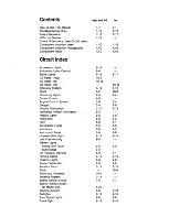
Страница 3: ...l 4 0 Engine Control System 3 0 3 4 Gauges 7 4 7 8 Ground Distribution 2 10 2 16 Handlebar Switch Illumination 9 5 Hazard Lights 9 6 9 8 Headlights 8 0 8 2 Horn 5 0 5 1 Illumination Lights 7 5 7 9 Indicators 7 0 7 2 Instrument Panel 7 4 7 8 License Plate Light 9 12 9 14 Low Fuel Warning 6 0 Marker Lights Fairing and Trunk 9 0 9 0 Saddlebags 9 2 Oil Pressure Warning 6 0 6 1 Parking Lights 9 12 9 14...

Страница 4: ......

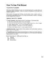
Страница 5: ...hematics show hawaII the components within a circuit work together current flow from the power source at top of page to ground at bottom of page switch positions shown II at rest as if the ignition was off special instructions Solid state Do not check resistance those circuits sharing a common power source or ground A System Description How the Circuit Works appears in the Reverse System section I...

Страница 6: ...ge PNK pink RED red WHT white YEl yellow Wires A wavy line means the wire Is broken by the binding of the book but continues on the next page Wire insulation can be one color or one color with another color stripe The second color is the stripe This means the current path continues on another page The arrow shows direction of current flow To follow the WHT white wire In this example you would turn...

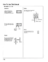
Страница 7: ...ctor Wires may not be used In all cavities Empty Cavity This means the connector 1 connects directly to the GRY component I This Indicates the connector connects to a lead pigtail wired directly to the component The name of the component BRAKE appears next to its upper SWITCH right corner 2 sa ssed Notes about component function follow its name Ground G This symbol means the end of the wire Is att...

Страница 8: ...rent flowing through Its coli I Fuses This means power Is supplied with the Ignition In ON II I l dentlflcat on GRN BLK Current rating Shield Normally Closed Contact Open Diode This diode allows current to flow only in the direction of the arrow I This represents RFI Radio Frequency Interference shielding around a wire The shielding Is always connected to ground 1 4 ...

Страница 9: ...1 5 ...

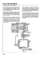
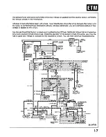
Страница 10: ... of the page The II hot label at the top of a fuse shows when the ignition switch supplies power to that fuse Each circuit is shown completely and independ ently on one schematic Other circuits getting their power from the same point or grounding at the same point are not shown However if other circuits actually share some wires with the circuit shown the shared wires of the other circuits will al...

Страница 11: ... know the fuse is good and voltage is available to the inoperative circuit You can then continue troubleshooting cont d To FUSE RELAY BOX on page 2 4 D To FUSE RELAY BOX on page 2 2 WHT i S25 HT MAIN WHT FUSE B 55A Page 3 12 _ 1 i i im i liii j ALTERNATOR Page 3 12 Starting System WHT RED RED YEl BATTERY MAIN FUSE A 30A lil G100 IT GRNiBLK _ _ L r ORN B BlK I BlUlORN LT GRN BLK V To FUSE RELAY BOX...

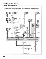
Страница 12: ...hich components share the same ground point C57 GRN GRN CRUISE CONTROL SWITCH ILLUMINA TION SE Only Page 9 5 II III G102 GRN GRN From 055 on page 2 14 GRN RIGHT HORN Page 5 0 GRN RIGHT G Page 9 3 C104 GRN GRN From S157 on following page GR _ GRN I GRN 1 S168 GRN I GRN GRN GRN GRN G100 PARTIAL 1 8 ...

Страница 13: ...n 12 for photographs Component Photo No AICV Solenoid Valve 8 Behind left fairing inner cover near front of fuel tank Air Jet Solenoid 2 22 Component or Behind right fairing pocket near ignition Connector Number control unit Number of Cavities 3 LdK1n t n I 45 Photo In Connector 0 22 BLU SE 38 U b 11 Behind left rear of seat In ec Ion Connector Color C10 22 WHT Asp 38 Below left rear of seat Compo...

Страница 14: ...s Turn on all components in the repaired circuit in all modes to make sure you ve fixed the entire problem If the problem was a blown fuse be sure to test all of the circuits on that fuse Make sure no new problems turn up and the original problem does not recur 1 10 Test Equipment Voltmeter and Test Light CAUTION A number of circuits include solid state devices Voltages in these circuits should be...

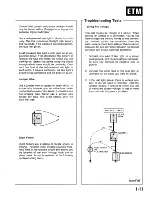
Страница 15: ...ight to each point If there is continuity the test light s circuit will be completed and the bulb will go on 1 Connect one lead of test light to a known good ground or if you are using a voltmeter be sure you connect its negative lead to ground 2 Connect the other lead of the test light or voltmeter to the point you want to check Jumper Wire Use a jumper wire to bypass an open circuit A jumper wir...

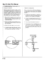
Страница 16: ...4 If the self powered test light glows there is continuity If you re using an ohmmeter low or no resistance means good continuity Testing For Voltage Drop Wires connectors and switches are designed to conduct current with a minimum loss of voltage A voltage drop of more than one volt indicates a problem 1 Connect the positive lead of a voltmeter to the end of the wire or to the side of the con nec...

Страница 17: ... ALL TIMES I FUSE I BOX FUSE REMOVED SHORT TO GROUND III1SWITCH BLl LOAD DISCONNECTED 1 1 1 SOLENOID i ii j u Testing For A Short With A Self Powered Test Light Or Ohmmeter 1 Remove the blown fuse and disconnect the battery and load 2 Connect one lead of a self powered test light or ohmmeter to the fuse terminal on the load side 3 Connect the other lead to a known good ground 4 Beginning near the ...

Страница 18: ...en the fuse box and the short 5 Beginning at the fuse box slowly move the short finder along the circuit wiring The meter will show current pulses through sheet metal and plastic As long as the meter is between the fuse and the short the needle will move with each current pulse Once you move the meter past the point of the short the needle will stop mov ing Check around this area to locate the cau...

Страница 19: ...e engine with the ground cable disconnected or you will se verely damage the wiring While You re Working Make sure connectors are clean and have no loose pins or receptacles Make sure multiple pin connectors are packed with silicone grease PackW lconegrease J I CAUTION Do not pull on the wires when disconnect ing a connector Pull only on the connector housings When connecting a connector push it u...

Страница 20: ...8 Tall 15 Accessory lights Instrument panel gauges Instrument panel Indicators Meter cornering lights headlight relays license plate light position lights side Position marker lights taillights reverse system control handlebar illumination 9 RVS Start 5 Reverse System 10 Acc 10 Air pump relay CB radio stereo cassette deck hazard lights Instrument panel Indicator illumination wheel speed sensor 11 ...

Страница 21: ... Used 7 Parking 10 Parking lights 8 Tall 16 Accessory lights Instrument panel gauges Instrument panel Indicators Meter cornering lights headlight relays license plate light position lights Position side marker lights taillights 9 Back Up 6 Stereo trunk light CB radio optional LCD unit 10 Acc 10 Stereo hazard lights 11 Ign Start 16 Bank angle sensor Charging system emission controls engine control ...

Страница 22: ... ignition switch is in P ACC or ON LILI Controlled by headset speaker control knob Indicates that sounds are present on the headsets and not the speakers To check air pressure in system press P Check button and time will be removed from display and air pressure will be shown in psi for American models and kg cm2 for Canadian models TMS When cassette player is loaded and radio is turned on this wil...

Страница 23: ...1 19 ...

Страница 24: ... 71FUSEI LT GRN BLK S140 1IIB L fi I C10 I I LT GRN BLK1t IIr p I A cas LT GRN BLK II I I RELAY I Illli r4i R bL_ t ci REOIYEL LT GRN BLK BLK BLK LT GRN C103 S101 c ct REDNELI I C71 REDNEL LTGRN BLK 103 r 7 R B li f URE S102 C I I weawea S104 1 REOIYEL LT GRNI n IICiiIII 311 BLK REOIYEL __ loC306 Asp REOIYEL C16 LT iC10S C107 1tLT GRN1t LT GRN LT GRNI GRNI LT GRN REOIYEL L 5_ C4 SE 1S 1lr __9 C1 B...

Страница 25: ...ii i i i i i iiiI LEFT CORNERING LIGHT RELAY BRN WHT Page 9 3 BRN f 10 BRN F To S113 on page 2 4 Continued on page 2 5 BRN WHT BRN WHYJC73 FI e S123 BRN WHY j See Headlights page 8 0 Marker Lights page 9 0 See Indicators page 7 0 Instrument Panel page 7 4 BRN WHT 2 1 ...

Страница 26: ...E To TAIL MAIN RELAY on page 2 1 BlK WHT GRN C10 WH G C87 1 1 J TURN SIGNAL FLASHER RELAY Page 9 7 WHT GRN g IGNITIONfS ITCHon page BlK BlK BlK 1IIIii 5 S106 S108 WHT GRNK K C57 WHT GRN C320 r FRONT BRAKE I I LIGHT SWITCH b l 2 J Page 9 16 WHT GRN if 2 2 2 ...

Страница 27: ...IIIII _IIIIIIII _IIIIIIII _ _ IIIIIIII IIIIIIII BlK FUSEI m I IIII 1 RELAY m BOX See Engine Control System Starting System Charging System Reverse System Cruise Control BRN RED C57 BRN RED RIGHT COMBINATION SWITCH cont d 2 3 ...

Страница 28: ...oioioioioI Page 3 13 BLU BLU BLK BLU BRN From IGNITION SWITCH on page 2 1 F BRN I C73 LT I GRNI VEL C103 lm A R ILIIIIi i y Page 5 5 1 S112 BRN C5S BRN I BRN S113 Itt ir f S273 BRN BRNT 1 _ S272 BRN BRi BR1C188 Optional r CENTER BRN I IliGHT _ ASSEM r lEFT I _ IBlY Op I 1 7 I SADDLEBAG Z Z Zi zl l 2J It12 L E r J tEr r2LY aM S142 LT GRNIYELI I C10 LT GRNIYEL c EB I Page 9 13 BRNI 1 S111 BRN I C77 ...

Страница 29: ... LIGHT Page 9 1 BRN WHT SPOILER BRAKE TAILLIGHT CONTROL MODULE Page 9 20 BRN WHT C75 BRN BRN WHT C76 BRN BRN WHT C82 BRN WHT 1 liill RIGHT SIDE TRUNK MARKER LIGHT Page 9 1 S209 S211 BRN GRN GRN BRN I LEFT ACCESSORY LIGHT Page 9 19 Il IIIII TRUNK LIGHT ASSEMBLY I I RIGHT ACCESSORY LIGHT Page 9 19 1_1111111 TRUNK LIGHT ASSEMBLY 2 5 ...

Страница 30: ...LK CB 8103 Transceiver Optional Page 10 11 LT GRN BLK WHT rC41 BRN RED J J Starting System Page 3 11 C5S C 1 11111111111111111 1RADIO CLOCK Solid state Do not check resistance RED I C41 RED BLK C71 C91 BATTERY MAIN rnzZ U ms FUSE A 30A RED VEL REDIYEL REDIYEL Fl aiii S101 III REDIYEL 1 li 1 G100 1 C89 GRN al fb aJl Page 9 18 RED VEL REDIYEL Instrument Panel LCD Unit Page 5 2 2 6 ...

Страница 31: ... II BRN WHTI C58 wp aee Gl00 BRN WHT BRN WHT C7D r I I f I 1lii JI RIGHT CORNERING LIGHT RELAY Optional Page 9 4 S421 ewe BRN WHT 1 4 C94 BRN WHT BRN WHT S420 r illll IIIE 3IIMWE lII IIII iIiid W II lIIIIIIIC B Er iIBI iIIIIi IrJiIIfi 3IiIic f C72 BRN WHT Oil Pressure Warning System Page 6 1 Headlights Page 8 2 Marker Lights Page 9 0 To S442 on following page cont d 2 7 ...

Страница 32: ...CH on preceding page BR N B R N L S442 BRN IT C10 BRN S413 BRNI BLK BLU BLU BLU RIGHT NOISE FILTER BLU C109 BLU I LEFT NOISE FILTER BRN BRN C56 BRN cas BRN BLU BLU r RIGHT 1 1 RADIATOR M I FAN I MOTOR L __ J Page 3 13 BRN S473 _ S472 BRN BRN BRNi C188 Optional 0 g ER r __ _ LEFT i 1 I 1 I I 1 t gP LY I BRAke I SADDLEBAG J IIt h LY 2 8 ...

Страница 33: ...rI RN WHT GRNkt J l ca7 t TURN r SIGNAL r I FLASHER L i a RELAY Page 9 9 WHT GRN A 7 S 8 WHT GRN1i AC320 r FRONT tlMJ H Page 9 17 W IG C81 WHT GR f 1 REAR r BRAKE l I LIGHT L SWITCH Page 9 17 RIGHT COMBINATION SWITCH BlK E To TAIL MAIN RELAY on page 2 7 2 9 ...

Страница 34: ...Ground Distribution G100 G102 103 and G104 Asp and SE Circuit Schematic GRN BLK LTGRN C22 SPEED LIMITER FUSE 65A Page 3 16 BLK INSTRUMENT PANEL GRN BLK BATTERY BLK LT GRN BLK BLK 2 10 0103 0104 ...

Страница 35: ... C55 on page 2 14 r7 7 RIGHT I CORNERING LIGHT RELAY Page 9 3 GRN C70 r 1 CRUISE CONTROL UNIT a Page 4 3 C135 C104 GRN GRN GRN From 5157 on following page GR 67 1IllIIIIIIIIII IIIIIlIlIIIIIII_ _ IIllIIIIIIIIII GRN I GRN S168 _1111111111111_ _ GRN I GRN r ENGINE CONTROL UNIT Page 3 0 GRN GRN GRN G100 PARTIAL cont d 2 11 ...

Страница 36: ...STAND SWITCH Pages 3 1 3 9 r 1 1 E J Rlc _ I TWO WIRE SPLICE I C23 C20 CB SWITCH DRIVER Pages 10 6 10 16 GRN GRN RADIOI CASSETTE DECK Page 10 1 r rll J C1 GRN t J i I IC192 _ _111111111111111 _ GRN I S147 GRN I S157 GR GRN GRN C23 GRN CBIRADIO SWITCH ASSEMBLY SE Models Only Page 9 5 llr j_ Ii lEFr HORN Page 5 0 llJI C179 GRN C89 TRUNK LIGHT SWITCH Page 9 18 IIJ GRN GRN BLK To 8167 on preceding pag...

Страница 37: ... LICENSE RIGHT SIDE ACCESSORY LIGHT ASSEMBLY PLATE TRUNK MARKER TRUNK LIGHT ASSEMBLY LIGHT Pages 9 13 9 16 LIGHT LIGHT Pages 9 11 9 12 9 16 Page 9 19 r 0 0 Page 9 13 Page 9 1 r _ _ _ __ _ _ GRNL RR GRN c GRN GRNt C75 HAZARD C77 S159 LEFT SIDE STARTER FLASHER LEFT SADDLEBAG TRUNK MARKER RELAY RELAY LIGHT ASSEMBLY LIGHT REGULATOR Page 9 7 Page 9 16 Page 9 1 Page 3 14 ilill fl ill IBJ GRN s R GR rfT ...

Страница 38: ... LEFT FRONT TURN SIGNAl LEFT FAIRING POSITION LIGHT MARKER LIGHT Page 9 10 Page 9 0 l 0 l GR r GR I J GRNIC98 GRN C97 GRN GRN S177 e GRNI G 5 S172 C24 GRN RADIO NOISE FILTER Page 5 5 r GRN i G r 182 GRNI GRN C10 Wiffi 9 GRN 111111111111 _ S166 LEFT HEADLIGHT POSITION LIGHT Page 8 1 I I I GRN L RNIG N I GRN e e S174 5173 GRNI S175 AIR PUMP ASSEMBLY Page 5 5 r I i 1 G I 1 106 GRN To 5168 on page 2 1...

Страница 39: ...2 15 ...

Страница 40: ...03 and G104 Int Circuit Schematic S168 GRN BLK GRN BLKI C10S CGG GRN BLKT l c72 GRN BLKJ S443 IEiBB iII iI il E e IEiBB iII iI il FUEL LEVEL SENDER Page 7 8 GRN BLK LTGRN BATTERY GRN BLK C22 BLK S552 _ GRN WHT BLK BLK e 0103 0104 2 16 ...

Страница 41: ...lg ERING III I al C70 GRN RIGHT I f 1 G I Page 9 4 GRN GRN GRNIa9 8156 GRN GRN FUEL PUMP Page 3 6 r 1 1 H j 1 C186 From 5152 on fOllowing page GRN GRN W From C72 on page 2 20 GRNIC49 7 GRN GRN I C127 GRN GRN GRN GRN 5468 GRNI G100 G102 cont d 2 17 ...

Страница 42: ...103 and G104 Int Circuit Schematic cont d I LEFT 1 1 g ERING 1 Optional Page 9 4 GRN C95 r s LEFT I I m ERING Optional C9G Page 9 4 GRN GRN GRN e S154 r2 2 SIDE C28 GRN GRN e GRNI8153 e S S152 GRN GRN M To 8151 on preceding page 2 18 ...

Страница 43: ...GRN I C RN GRN 8449 1 8450 5 iiGiiRN _ G R NJCIO cont d 2 19 ...

Страница 44: ... S471 C67 GRN LEFT FAIRING MARKER LIGHT Page 9 0 GRN GRN RIGHT FRONT TURN SIGNALI POSITION LIGHT Page 9 10 l lJ J S476 RIGHT FAIRING MARKER LIGHT Page 9 0 GRN LEFT FRONT TURN SIGNAL POSITION LIGHT Page 9 10 GR I I C98 GRN GRN GRN GRN S177 GR NlC72 GRN K To 5155 on page 2 17 GRN S175 GRNI C24 2 20 ...

Страница 45: ...2 21 ...

Страница 46: ... Angle Sensor BLK WHT BLK WHT BLK WHT 3 0 BLK LT GRN d P we aw wr RIGHT COMBINATION SWITCH C120 1II ilI iiIBI BLK LT GRN AIR JET SOLENOID 2 IGNITION COILS SPARK PLUGS BLK LT GRN d P BLK LT GRN C43 B TGRNI Charging System C119 AIR JET SOLENOID 3 GRN Instrument Panel Tachometer ...

Страница 47: ...stem r GRN WHTl1 GRN WHT R Reverse S t N BlK WHT RED GRN GRN ORN Indicators S267 1 e lr llr dl II e lil1 RED VEL RED WHT ORN GRN ORN GRN WHT VEL BLK VEL BlK S185 e r WAIl C28 r aBi1 IT GRN RED GRNI Cruise e8186 ORN RED WHT Control GRN WHT C28 1 S144 e SIDE STAND LT GRN RED RED I SWITCH WHTA _ C69 RED GRN WHT ORN II I I GEARSHIFT SENSOR cont d 3 1 ...

Страница 48: ...ni C18 GRN B BLK BLU I BLK BLU I BLKI i7 A TOR KI 1 i i 8 A ToRD LT BLKIBLU I C178 LT BLU C185 184 BLU FUEL M PUMP IC127 GRN BLU j C178 GRN BLU I IN LINE I JCAPACITOR D GRN l C178 GRN C191 PNKI r _ J L C49 resistance I PULSE PNK WHT GENERATOR C314 2 f T SOR 0 I TW C314 CRANKSHAFT BLU GRN BLK GRN BLK VEL r JC63 S301 GRN BLKI l_ C60 GRNIBLK BLU S196 l j l 3 2 ...

Страница 49: ... cont d 3 3 ...

Страница 50: ...hometer YELIBLU IGNITION COILS YELIRED YELIBLU BLK LT GRN we we we S481 BLK LT GRNl T C72 BLK LT GRN C120 BLK LT GRN BLK LT GRN C119 eJiiiWawe S489 BLK LT GRN SPARK PLUGS Starting System Bank Angle Sensor BLK WHT C57 BLKIWHTI S495 _ iC 3 BLK WHT ii_h BLK WHT BLK WHTI Bl K WHT S184 3 4 ...

Страница 51: ...BLK LT GRN BLK LT GRN C315 AICV SOLENOID VALVE cont d 3 5 ...

Страница 52: ...rcuit Schematic cont d BLK BLU PULSE GENERATOR 2 PULSE GENERATOR 1 WHT BLU WHTIYEL _1IIiiI Y_ _ J C314 PNK WHTI C60 11 NSOR C314 Il f T C184 j 10 BLK BLU BLK BLU BLK BLU C185 BLU FUEL 111 11111111 PUMP C186 GRN r FUEL PUMP GRN 3 6 ...

Страница 53: ...3 7 ...

Страница 54: ...uit Schematic I0iTIITm0S000mrt REVERSE LEVER SWITCH l C57 C92 VEL RED BLK WHT EWHTIBLU Reverse System VEL RED Reverse S19 8 YELlRE assette VEL RED Deck CB Transceiver To STARTER RELAY A To S303 on following page on following page 3 8 ...

Страница 55: ...f bt ASSEM Reverse RED1 L j B LY System RED C312 YEl REDI I C32 BRN RED YEl RED _ _ _ _ _ _ C30 YEl RED t r t I i E 2 _11 BLK REDf u IC30 1 C 31 3 W GRN RED C32 Reverse LT GRN REDr BLKi REor BW REDJ GRNffiEDl System GRN REDl LT GRN RED Y I Ii Reverse LT GRN RED U GRN ORN Y C32 System w S306 GRN REDJl LT GRN REDl l C94 GRN RED i C32 C326 Engine uiiiij 8hen LT GRN RED t C181 lr A w we Reverse GRN WH...

Страница 56: ...Starting System Int Circuit Schematic GRN 3 10 C57 YELJRED S19 i lf iI E YELJR To STARTER RELAY A on following page BRN WHT To C66 on following page Radio Clock CB Transceiver optional ...

Страница 57: ...RN WHT C41 ill I 1 ER BRN REDIC41 l T GRN REO r S373 u I M_ro M i C72 I 2 c 6 E I c 6 E I I Engine GRN REO iIlIIIiIIt a _ iII l ilT GcRaN RcE O iiiii I I 3 l S _ _ J I S486 AC94 GRN REoI C326 i 1I rf sed GRN WHT C325 Engine Control C93 System If 1 GRN WH RN WHT a ndI cators _ a IIf I a 1 __ S557 GRN WHTI VEL BlK 04 C28 GRN WHT VEL BlK I ISIDE STAND SWITCH Sii ri QffifI C28 jl im j l G100 IT GRN RE...

Страница 58: ... C33 W C10 WHT GRN1 C11 r BANK ANGLE SENSOR 1 111IN LINE APACITOR MAIN FUSE B 55A m IT1 GRN BlK BlK lT GRN BlK lT GRN E II S180 S480 BLK LT GRNI C43 WHT Engine Controi System Asp and SE Int Starting System WHT BlK BATTERY llft o _ t b l a o _ iU l n 1 1 Iii G100 iljlr fl 8251 3 12 ...

Страница 59: ...t Schematic oi IHOT IN ON I 111 lIil BlK BlU RIGHT RADIATOR FAN MOTOR LEFT NOISE FILTER IILEFT RADIATOR I i2 I FAN MOTOR BlU BLU a2 l c l o 9 Cll0 BlU BlU BlK BlK LEFT RIGHT NOISE NOISE FILTER FILTER BlK C110 BlK BlK 3 13 ...

Страница 60: ...hematic WHT VEL RED To STARTER RELAY B on page 3 16 To S227 on page 3 16 To REVERSE RELAY SWITCH III lIIl on following page BRN RED S302 ki J ii IIIe iIII a il a 1lle illlIE iiII iI IIIM iIIIIIIIE e BI IIIe iIII iiI ii iII 3 14 ...

Страница 61: ...tors BLUlREol S E REVERSE VEL RED BlUlRi 2 SSURE WHT BLK D I O D E 4 SWITCH J BLU y C92 S B Y e sfbove WHT II BLK WHT C32 BLK WHT f Or YEl REO 0 1 0 2 S303 e wra te a II w S310 kg cm2 BLK l I 1 From S302 on WHT WHT L J BLU BLK 1t C73 YEl REO preV IOUS page WHTJl C32 BLK WHT C66 YEl REO BRN REO 1 1 1 l j N r r t o l jl SJ MENT 1 1 5 8 0 117 3 I R EVLIAicyR E i l f J l i i i i 1 i l i i i 1 i i i i ...

Страница 62: ...ELAY on page 3 14 A on page 3 14 WHT BlU r z Z Z iiii ____ ED RED C313 IN LINE 1 1 1 FUSE A 1 1 SA PNK BlK yC313 GRN REDJl 2 GRN R V To REVERSE DIODE ASSEMBLY on previous page STARTERI REVERSE MOTOR BlK GRY BATTERY BlK SPEED LIMITER FUSE GSA rfT II e r 2 rou I t i i If 0100 VEL VEL 1 WHT1r RT C312 WHT r R I C32 AC42 IlllllllllllllS EL VEL C312 VEL C32 VEL rC42 S307 t IlI t I 3 16 ...

Страница 63: ...efly en ergize the reverse relay switch The reverse relay switch contacts close to provide a one second path to ground This pulls the contacts of starter relay A closed At the same time that pin 14 outputs to reverse relay switch the reverse control unit grounds pin 7 LT BLU which grounds the starter relay regulator This provides the hold in current path BRN RED to keep starter relay A s con tacts...

Страница 64: ...eed limiter fuse 65A do self test B pin 12 Faulty reverse control unit Replace with known good reverse control unit Reverse system operates for only a few No voltage to starter reverse motor do seconds then quits Reverse indicator self test A pin 13 turns off or reverse system doesn t op No control signal to reverse control unit erate and reverse indicator lights from starter reverse switch do sel...

Страница 65: ...s do self test F If all the above is OK check red circuits to power relay controls for battery volt age with ignition ON starter reverse switch in REVERSE and starter reverse switch pushed If voltage is not present service circuits for an open Reverse system operates above 2 5 Inoperative speed limiter relay do self km h down inclines test A pin 2 Reverse system operates but reverse No control sig...

Страница 66: ...age should drop 5 volts If not replace reverse control unit If both measurements are correct go to self test F Starter Reverse Motor Input PNK Varying voltage present with ignition switch in ON reverse lever switch in REVERSE and starter reverse switch pushed If not check in line fuse A 5 amp If fuse is good check circuit for an open If all measurements are good do self test A pin 11 Starter Rever...

Страница 67: ...e Voltage should drop below 5 volts If not replace reverse control unit If both measurements are correct do self test F Ground Input GRN Check for continuity to ground G100 If there is no continuity repair GRN circuit for an open If OK go to next diagnostic step Neutral Switch Input LT GRN RED With transmission in neutral check for continuity to ground If not check LT GRN RED circuit for an open I...

Страница 68: ...h If all measurements are OK go to next step 4 Service WHTIBLU circuit for an open SELF TEST D Side Stand Switch 1 With ignition ON and side stand DOWN check to see if side stand indicator lights If yes jump to step 3 If no go to next step 2 With C28 disconnected check for continuity between GRN circuit and ground G100 If yes go to next step If no service GRN circuit for an open 3 Disconnect C28 a...

Страница 69: ...ssary If all measurements are OK go to self test H SELF TEST G Speed Limiter Relay Test 1 With relay disconnected apply 12 volts across the coil and measure continuity across contacts continuity should exist If not replace speed limiter relay If OK go to next step 2 Check continuity of WHT circuit and YEL circuit from contacts and repair if necessary If OK go to self test H SELF TEST H Reverse Res...

Страница 70: ...Cruise Control Circuit Schematic WHTI RED GRN RED Brake Lights 4 0 REAR BRAKE LIGHT 1 4 1 1 SWITCH WHT BLK ...

Страница 71: ...WHT WHT BLK WHT l C57 BLK WHT I r S188 1 IIIillllil E WHT BLK WHT I SENSOR BLK WHT Engine GRN S S195 II Control I C11 WHTll System GRN To RIGHT COMBINATION It C55 1 1 11 11 SWITCH on follo ng page C66 0100 S240 W r INSTRUMENT BLUIWHT WHTIBLK S 3 lS a 8244 I I BLUIORN OJ OJ OJ OJ J A S238 l BLUIWHT C66 r diii c Q BLU WHTI BLU ORN I C55 C72 VEL RED BLU WHTI BLUIORNI YEL REOr B U H r C33 _ _ _ _C2 35...

Страница 72: ...Cruise Control Circuit Schematic cont d Handlebar illumination BRN WHTI 057 lS1umREAR BRAKE 1 14P il CRUISE CANCEL iiIioiiioiililSWITCH BRN RED BRN RED 4 2 BLK VEL WHT BLU WHT VEL ...

Страница 73: ...From CRUISE VALVE RELAY on preceding page ACTIVATOR CABLE CRUISE CONTROL ACTUATOR BRNI WHT CRUISE BRNI CONTROL WHT VALVE 1III IclI iiI UNIT C131 GRN 4 3 ...

Страница 74: ...Horn Asp and SE Circuit Schematic HOT AT ALL TIMES RELAY BOX WHT GRN 8110 Turn Signal Cancel Control Unit WHT GRN LTGRN 5 0 LT GRN LT GRN 8 1 C 1 29 l io Ig C128 I GRN I C191 1 1 t I L u I C191 GRN ...

Страница 75: ...Int GRN S468 GRN I Gl00 I FUSEI RELAY BOX ii iiWjEt Ot ttibUttoh Pi 2 j LT GRN 5 1 ...

Страница 76: ... R C f _EilII_ iCr C3 01l 6 i1 ACS Plll il a RED l T GRN IT GRN BlK REDIYEl VEL BlK C4 SEl 18 9 C1 Rill il ill i_1i I C2 l T GRN BlK BlK IT GRN S278 e G PNK G r 1C71 lTGRN BlKl r r C6 RED BlK 1 C66 VEL l T GRN BlK s K li wiW RED C91 S104 ell a mi1nbutiQn VEL BlK IT GRN BlK page O r I PNK MemorY I rr 1 1 Volt IgnttlOn I UNIT I I I Input t tffl t l t Input I Solid I GF NJBLK 1oioI Ground I 1stllte I...

Страница 77: ...5 3 ...

Страница 78: ...0 00 m 0 m INSTRUMENT GRN RED BLK GRN LT BLU GRN RED Nl LU y C91 GRN BLK I l C72 C16 i l 5 i__ illll BLK GRN LT BLU C66 GRN BLK U II IIAIR PRESSURE SENSOR Gl00 LT GRN BLK I ii J Wik Oi hibUdon lIICIIllllCile S103 g f LT GRN BLKi GRNIYEL LT GRN BLKr LT GRN BLK Instrument dM S278 Panel LCD 1 Unit LT GRN Cl03 5 4 ...

Страница 79: ...UMENT PANEL BRN WHT C91 BRN WHT BRN WHT If S237 Wjttr wij6M U jf BRNIWHT1 77 i I P i l IiH BRN YEL LT GRN BLK D ENSION RE E RN BIL C1 R PUMP SOLENOID SOLENOID ASSEMBLY VALVE VALVE l GRN GRN GRNI GRNy C182 GRN IflII m I i t ijhij GRNl C1 0 I lllli I li WW WN GRN iil i li 1 i G100 G100 5 5 5 ...

Страница 80: ...Low Fuel and Oil Pressure Warning System Asp and SE Circuit Schematic 1 6 0 ...

Страница 81: ...Int Oil Pressure Warning System C66 BlU REoI C55 BlU REoI C22 rs0 s Oil PRESSURE SWITCH Open above 1 3 psi 0 1 0 2 kg cm2 BlK 6 1 ...

Страница 82: ...cuit Schematic IHOT IN ON I 7 1III S105 I BlK HOT AT All TIMES I _ it Ii SRN WHT BOX BlK BRN l I tj II GRN G100 REVERSE LEVER SWITCH BlK WHT L WHT BlU i C92 T WHT BlU l BlK WHT f S303 Headlights Reverse System IN r i l t j 7 0 ...

Страница 83: ... m BLUI ORN J UI GC UI WH ORN 8239 8244 BLU WHT l BLU ORl C66 BLUlWHTI BLUIORNI Cruise Control GRN 0100 Headlights 7 1 ...

Страница 84: ...Indicators Int Circuit Schematic FUSEI RELAY BOX GRN GEARSHIFT SENSOR I I I I I I I BLK BRN 7 2 ...

Страница 85: ...7 3 ...

Страница 86: ...Instrument Panel Gauges Illumination Lights Asp and SE Circuit Schematic FUSE RELAY 1 BOX YELIBLU C72 7 4 ...

Страница 87: ...WHTi iiirl I 1i 8121 BRN WHTI C73 BRN WHTJ BlK BRN 8123 ed t Gauges BRN WHTI C66 BRN WHTi 8228 t aIlE lBR IIIB iIIE 3B i1 i1 iIllll R IIIM iII 0100 BRN WHT GRN BRN WHT GRN BRN WHT RELAY BOX 8290 GRNIC66 GRN GRN 0100 7 5 ...

Страница 88: ...Sensor Circuit Wheel Speed Circuit Schematic INSTRU MENT PANEL G103 LT GRN G100 GRN BLK LT GRNIBLKIC16 LT GRN BLK VEL RED 16 It riripot 1 TTE I II IIIII I IDECK Solid state C33 Ii Do not check resistance 7 6 ...

Страница 89: ...ngine Control Unit see page 3 0 Asp SE 3 4 Int wHTNELr l C63 GRN BLK C49 WHT BLK WHTIYEL WHT BLU PULSE GENERATOR 1 li C33 WHT BLK C135 II1III _________ 8301 J BLU 1 lJIII I PULSE GENERATOR 2 GRN BLK Asp SE S196 w W Int S496 GRN BLK W 6gi6 i i ifl i E H fH m m l CRANKSHAFT 7 7 ...

Страница 90: ...Instrument Panel Gauges Illumination Lights Int Circuit Schematic YELIBLU 7 8 INSTRUMENT PANEL ...

Страница 91: ...HT BRN WHT 11Ii 1 1 1 tll jiii f 8 S420 BRN WHT1 T C72 BRN WHT S430 e IP II 11 3 E lI Marker Lights BRNm 1 C66 BRN WHT BRN WHT 1IIIII IIIl iIII S609 0100 GRN INSTRUMENT PANEL S592 e I t istldt S591 GRN I _ ellililii GRN I IIIIU S590 GRNIC66 GRN GRN 0100 7 9 ...

Страница 92: ...P IlEtAYii j il T lfiili I Iil l n NliIWln 1e e 1 s t E I l J flll I tt t tt ttttttttttt t I I liiW l 2 E W tm mmm I I1 Mfj t I mrl ttl t l GRN BRN WHT FUSE RELAY Illliilll BAN WHT iS415 BAN GRN I E ie we l il iII S212 G100 BRN WHT ARIGHT n POSITION LIGHT GRN Indicators Neutral Indicator To FUSE RELAY BOX on following page 8 0 ...

Страница 93: ...Ilqi B CS4 1 1 J Wjj i b10W m 10m10100 FUSEI r 2 I RELAY I WHT WHTJBLU 11 li il iiiiiilllillili wlil I I i G100 f G100 WHTIBLK 1I H B LK1 C24 C66 S202 BLU BLK 0 l BLU SrJ MENT r WHT BLK I LOW HIGH l III DLlGHT POSITION I LIGHT GRN GRN GRN GRN _ S174 S173 GRN I S G R N s175 111 GRNI I T C24 GR N GRN GRN S172 II1II _ S166 GRN Isee GrOoocf Sl N I C55 l See Ground I Distributtori page Z 14 Gl00 8 1 ...

Страница 94: ...cuit Schematic FUSE RELAY BOX GRN GRN S415 I BRNIWHT V L eq S212 BRN WHT BRN WHT I RIGHT I LEFT HEAD HEAD _ LIGHT _ LIGHT POSITION POSITION LIGHT LIGHT GRN G100 BRN WHT C57 BRN WHT To FUSE RELAY BOX on following page 8 2 ...

Страница 95: ... 0100 WHT BLK WHT BLK GRN RELAY BOX 8 3 ...

Страница 96: ... BRN WHT h Panel 8430 IItIlll BRN WHT R I BRN WHT 8213 iI I iiII iiII El BRN WHT I BRN WHT I Headlights 8212 C68 BRNIWHT1C97 BRNIWHT BRN WHTI LEFT FAIRING d2r RIGHT FAIRING t MARKER LIGHT MARKER LIGHT GRN GRN GRNI C97 S NTC88 GRN Right Front Tum 8471 I Signal Position Light Left Front GRN Turn Signal 8176 GRN Position Lights 8476 8172 GRN Instrument Panel 8477 illumination GRN 1 GiiilR N Headlight...

Страница 97: ...8264 II r 11 8268 w w 1I l BRN WHT BRNI WHT BRNI WHT BRN WHT BRNI WHT BRNI WHT RIGHT 81DE TRUNK MARKER LIGHT GRN GRN GRN 8271 8270 1 GRN S IC82GRN 8459 GRNI _ _ _ _ _ _ _ _ _ _ _ _ _ G R 8161 I 8461 GRN GRN 8149 __ 8449 1 GRN I C10 GRN 1111 C192 GRNI U j j ii stdo ri Jtj j lilillitll li G100 GRN 8267 8266 1 GRN C86 LEFT 81DE TRUNK MARKER fI IillilltIELill illillllil llEElIEJ LIGHT L Asp and SE Int...

Страница 98: ...IIIiIII I Automatic 1 Level Control LT GRNIYEL I C10 LT GRNIYEL 11 IN LINE IODE LT I V G100 BRN BRN S112 BRN Sl11 I BRNl t I C77 License BRN Plate Light C78 BRN BRN 11 11 INVERTER fI Optional GRN LEFT SADDLEBAG MARKER LIGHT RIGHT SADDLEBAG MARKER LIGHT GRN BRN WHT GRN BRN WHT 9 2 ...

Страница 99: ...Cornering Lights Asp and SE Circuit Schematic r 11111111 I t BRN WHT LT BLU WHT w wr a 9 3 ...

Страница 100: ...Cornering lights Int Circuit Schematic BRN WHT 0100 1111111111111111111 LEFT t COMBINATION SWITCH ORN WHT BRN WHT S416 BRN WHT 9 4 ...

Страница 101: ...Handlebar Switch Illumination Circuit Schematic BAN I WHT C94 0100 8115 FUSEI RELAY BOX 9 5 ...

Страница 102: ...i iIII I Ii 5115 0100 BRN WHT BRN WHT C94 BRN WHT ANGLE SENSOR WHTIBLK WHTIGRN S110 WHTIGRN K HT RNi S WHTIBLKr C90 Horn Switch C99 TURN SIGNAL WHT BLK WHT GRN CANCEL 11111CONTROL UNIT Solid state I Do not check PNK LT GRN WHT GRN t resistance Ir p C99 PNKYLT GRN WHT Y GRNY t Y I l C90 PNKILTGRNIWHTI l _ON 5 C181 C93 PNK LT GRN WHT GRN I 9 6 ...

Страница 103: ... BLK PNK WHT To 8215 on page 9 10 Q ORN WHT ORN LT BLU S222 111111111111 S221 III ORN 1 C93 OR LTBL To 8285 on page 9 11 To 8223 on page 9 11 i v HTI GRN BLU BLK 22 JII llliLT GRN BLK i Brake Lights WHTIGRN WHTI GRN WHTI GRN 9 7 ...

Страница 104: ...t Schematic IHOT IN ON I I HOT AT ALL TIMES I r I 1 I au TAtLlMETERI I BOX I POSmON I L FUSE I r 8105 I lSA I Se f poWe r GRN BRN WHT iiiltill 8415 0100 BRN WHT BRN WHT BRN WHTi8421 C94 C94 LT BLU W tORN W To 5217 on To 5215 on page 9 10 page 9 10 9 8 ...

Страница 105: ...11 111 LT GRN BLK C10 LT GRN BLK C8S ilill R NJ C8S GRN 0100 PNK WHT GRY 0100 ORN LT BLU LT BLU 8222 8221 1111 ORNl eg3 OR LTBL To 5285 on page 9 11 To 5223 on page 9 11 ORN cont d 9 9 ...

Страница 106: ...5 LT BLU C67 GRN LT BLU ORN ORN C98 8220 LT BLU 1LT BLU WHT oRN WHTII C66 LT BLurl 6 LU WHT LEFT FRONT r RIGHT FRONT TURN SIGNALI TURN 8IGNAL POSITI R IONu R l__ T i INSTRUMT o ION GRN 8176 8476 Asp and SE Int Left Fairing Right Fairing Marker Light Marker Light GRN L RN _ _G R N_ S177 GRN GRNJC66 GRN GRN GRJ I 1 8172 8171 GFtN 8477 8471 C55 GFI I i m9H 11 lil i GFIN G100 9 10 ...

Страница 107: ...____IIIIiIIIIIIIiI 8223 From C93 on pages 9 9 and 9 7 R ORN C55 ORN C73 ORN 5 p I 8285 I LT BLU l LT BLU 5 1l iiI From C93 on pages 9 9 and 9 7 8 LT BLU GRN 8158 8458 GRN 8159 _ _ GRN GRN G100 Asp and SE Int 9 11 ...

Страница 108: ... Alec I Li __ J BRN C58 BRNI BRN R I H C10 I BRN S113 s 1 Left Rear BRN WHT S208 BRN WHT BRN Side __ _E II iiII i_ ICilIII i_ iI S BRN I C84 Marker BRN WHTI Light TC85 C75 BRN BRN S272 GRN l S209 Left Accessory BRN Light BRNI elSS Optional BR fl ER rtf II ill l E 11 IIJ i lll HT ASSEMBLY I TAtl fOOAk ILLIQHTI ASSEMBLY frA t OOA ILLIGHTI Optional Lii __ J L J GRN GRN I C188 Optional GRN Accessory G...

Страница 109: ...GRNIYELI LT GRNIYELI Cl0 I c 6 E S112 BRN BRNI _ _ _ S111 Right Rear I BRN WHT S210 BRN WHT Side BRN w _ lI_ 3IW _ __ Marker C77 BRN WHT1 Light I TC76 BRN BRN GRN Right C78 S211 Accessory BRN Light BRN GRN GRN S157 GRNI C78 l C76 GRN GRN GRN I GRN BRNlC56 er SE 8159 _ _ 9 B NI mn llr J i I il J llj f j f l I jr GR 1 G100 BRN GRN GRN 9 13 ...

Страница 110: ... iBI iII BR ilN WIIIl iiIIHT iIIIIIIIII IE iI 5 BRN Side we Marker BRN WHTI Light TC 8 5 1C75 BRN BRN 8472 BRN BRN1 8209 Left Accessory Cl88 Optional i Light LY r II lli LYflJlJf I l L HT 0 tional I TAllt BRAKE I I tAll fBRAKE P 1 iiiI _ _ _ u GRN GRN I C188 Optional A GRN GRN GRN GRN ccessory 1 lIIIIIIIIIIIIlIIIIIIIIIIIrBj5 Lights 8460 C75 GRN GRN GRN _ 11111111111 _ _ 5 8475 C85 BRN 9 14 ...

Страница 111: ...9 15 ...

Страница 112: ...cuit Schematic REAR BRAKE I r I LIGHT 8WITCH WHT GRN 8109 2 Oi Oi 8 107 L l irtll ll l GIOO Z C3flwl T cal C321 GRNIYELI C57 GRNIYELT J C81 GRN ORN GRNIYEL_ 1 3111 11IE _ E e HIIIIIIIe iIII e 8 i1 8243 GRNIYEL Cruise Control 9 16 ...

Страница 113: ...Int GRN GRN r sJ m REAR I BRAKE hlMi 1 LIGHT Liiiiiiii SWITCH 9 17 ...

Страница 114: ...ili I RED VEL REDIYEL Asp and SE Int 9 18 REDIYEL eTRUNK rb nallnt GRN BLKI lI 1 VANITY i r 1 I Optionallnt GRN BLK fjBITRUNK s f Int Closed when I trunk lid Is GRN BLK opened I C89 GRN GRN 0100 CB Transceiver Optional REDIYEL Radiol Cassette Deck Instrument Panel LCD Unit ...

Страница 115: ...ght BRN WHT Brake Tail BRN WHTJl TC75 19ht TC76 BRN BRN SE ONLY BRN GRN RI h B k 1 8209 8211 t g t ra e IIlI l1li Light GRN1 GRNI Taillight LEFT ARLII G H T880RY I 880RY GRNT Brake Lights GRNr GRN GRN 8457 Right Brake __ 8160 Taillights 8157 IIIIIIIIIIIIIII Light 1 8460 I GRNI Taillight GRN C76 GRNT GRNI C75 8458 GRN Right Rear GRN 18459 8158 Turn Signal ______Be 8159 GRNI Light Left Brake Light T...

Страница 116: ...Spoiler BrakelTaillight SE Only Circuit Schematic NOTE 6 volts taillight 12 volts brake light 9 20 ...

Страница 117: ...9 21 ...

Страница 118: ...state Do not check resistance C7 T I GRNI BlK 16 iC1 r l 1C2 IT GRN BlK A t tl S277 L v o trol I Cruise WHTIBU RED WHT BlK GRY G l I I S238 1 1 WHTIBl1 I C66 C73 4 Ii t C71 IT WHT BlK GRNI I BlK nstrument Panel I IT GRN BlK RED WHT BlK BlK GRY S104 _ I iBIE iIIIIB II l1llllll IT GRNI BlK WHT BlU 4 t __ L __ __ C91 WHT BlK GRN GRY 10 0 ...

Страница 119: ... I t nce r f f C130 arouijd BLU GRN GRY BLK RED GRN BRN BLK 1b rtfibUH C71 U p zq jt BLU GRNr R LK E LK GR BL NI r a RED l r J LEFT tiLU I iHN t LEFT RIGHT RED GRN t RIGHT FRONT FRONT FRONT FRONT SPEAKER TWE ETERi SPEAKER TWEETER Optional Optional l R w _ J l w _ I J S288 S281 BRN WHT Solid state Do not check resistance cont d 10 1 ...

Страница 120: ... I I I I BLKC_ VEL BLK I I I I I RED I BLU I I I I r LT GRN RED VEL GRN BLK LT GRN RED S262 E ilIIR ilI iiI il GRN BLK C10 C12 GRN BLK RADIOI CASSETTE DECK Solid state Do not check resistance GRN BLK LT GRN RED VEL BLK WHT BLK VEL RED 1 IIIIIIIillilliiPASSENGER HEADSET I In Helmet 10 2 ...

Страница 121: ...LT GRN RED 5 a YEL BlU BU Y RED BlKY VEL REDI C21 VEL RED 8260 AP ____ C304 C ANTENNA lliil IC lljlljl iii III ii i ilillllllllililiiiili lli lil i RADIOI CASSETTE DECK Solid state Do not check resistance I SE ONLY I 10 3 ...

Страница 122: ...tic cont d Speakers SE BLUIYEL REDIYEL RADIOI CASSETTE PLAYER GRYIBLK BLU YEL e BRN BLKL ____ C130 FADER BRN WHT GRY I GRY BLUI GRN 10 4 r Me BRN BLK we we 1 BLUI r YEL 1SPEAKER at IGRY WHT BRN HTl YEL f C302 RIGHT REDI REAR YEL s p EAKER BRN WHT ...

Страница 123: ...10 5 ...

Страница 124: ...BlK REDIYEl Turn Signals IT GRN BlK Reverse System Radio Cassette Deck Starting System Fader may be Installed here See page 10 1 If equipped RIGHT FRONT TWEETER Optional I HOT IN ON PARK AND ACC IT GRN BlK IT GRN BlK 8140 Automatic Level Control 10 6 ...

Страница 125: ...I ANTENNA r W H TIT ORN I GRY S283 CB SWITCH 1 GRN 1C20 PASSENGER S CONTROLLER S224 oBRN l GAY 18284 C20 WHT GRY I r 4 JIr ORN __ J __ C304 WHT 10 7 ...

Страница 126: ...RNI BLK IHOT IN ON PARK AND ACC IHOT AT ALL TIMES I I HOT WITH IGN CRlJlSE RELAY ENERGIZED I rl I _ lf _ l a s i _ E _ _ I _ _ _ _ _ rIIIT 1 1IiJ ii lltil ATION REDIYEL rRilil 111 nlll 1 LT GRNI BLK LT GRN BLK REDIYEL YEL RED RADIO CLOCK Solid state Do not check resistance 12 rC1 GRN 111111111 1 i R 1 M l t t GRN G100 10 8 ...

Страница 127: ..._ iI f I WHT 1SHIELD 1 1 BLK GRN BLK Input from RADIO fIIII CLOCK cavity 15 and MUTE SEARCH SWITCH I _ I IT r BlKrt I I 1 1 1 1 SHIELD I I 1 1 BlK BLK L I RED WHT I SHIELD _ _ _1 BLK BLK _ AUXILIARY liy IIII illl I II I 1 ECTOR 7 10 9 ...

Страница 128: ...BLK LT GRN RED GRN BLK I I YEL LT GRN RED I I SHIELD I S262 d I I I SUO I j YEL LT GRN RED GRN BLK C10 YEL LT GRNI RED I I I I SHIELD I I YEL I I I I I j 5 r 17 BLKL I I I I I REDI I BLU I I I I BLKl L I I I I I REDI I BLU I I I I _ BLK w a a ft s O 6 L w Wijfj9ijf r v e 99hVAll W P9 mt ll t iP c12 _ 1 1IIIIIIII 10 10 ...

Страница 129: ...tate Do not check resistance 3 l1 GRN BLK 13 o Driver s GRN BLK r 1III lae iBIC H Headset on page 10 9 GRN BLK aear w II MIC GRN BLKI S261 T C21 GRN BLK S197 1E3 1CII GRN BLK BLU BLK GRN BLK RED BLK LEFT COMBINATION SWITCH Y ELIRED ANTENNA CB Transceiver 10 11 ...

Страница 130: ...lid state Do not check resistance With Rear Speaker optional 13 14 6 5 1f1 C1 resistance GRN se Grobmrm BlUlGRN GRY BlK RED GRN BRN BlK I Oi trib uttori GR I P Q gfH t 4 _ 4 It C130 0100 I II I i l i i ij llltl l I I I t l I I I I l i I II illllll11 I11111 I I i 1 1 FADER 10 12 ...

Страница 131: ...runk Light REDIYELI _ VEL RED VEL RED Startln IT GRN 8102 1 E i11E3I 81981ee syste BlK CB YE ED 8103 _ rae Transceiver Radio Clock I optional YEL RED l T GRN BlK1 REDIYEl IT GRN BlKI EI I C306 r CB BLKF f N 1 B NT p r Y LI TI h C4 l _ l__ l __ L__l __l __ __ _ J C17 GRY r 1 1 _ resistance GRY BLKr L l R 1 E R C130 _____ C6S GRY BlK BlU GRN BRN BlK RED GRN LEFT FRONT Lrt SPEAKER Fader may be instal...

Страница 132: ...Citizen Band Radio Int Circuit Schematic cont d ANTENNA T WHT r _ 8283 ORN GRY WHT _ 8224 1 8284 ORN GRY 1 __________ _ C20 WHT 10 14 ORN GRY 11_11 Mill ill m 1ICB I SWITCH C304 PASSENGER S CONTROLLER ...

Страница 133: ...II FAEE PlJ B I REVERSE I t _ J T _ J YEL RED C57 YEL REDl YEL RED S198 J jlliilli ilIIiIII REDIYEL REDIYEL S101 Trunk Light REDIYEL a REDIYEL seErpO 1 02 r alea rijij I RN i ll 1 S103 I HOT IN ON PARK AND ACC LT GRN BLK LT GRN BLK S140 Automatic Level Control LT GRN BLK Turn Signals LT GRN BLK LT GRN BLK REDIYEL YEL RED Fader may be Installed here See page 10 1 If equipped RIGHT FRONT TWEETER Opt...

Страница 134: ...Citizen Band Radio SE Circuit Schematic cont d CB SWITCH DRIVER ANTENNA C4 G I 0100 GRN WHT GRY ORN 1 1 C304 WHT 10 16 ...

Страница 135: ...10 17 ...

Страница 136: ...ind left fairing inner cover on thermostat housing 11 0 Cruise Control Actuator 6 Behind left fairing inner cover Cruise Control Unit 20 BLK 36 Below center rear of trunk Cruise Control Valve Unit 5 Behind left fairing inner cover on left side of fuel tank Cruise Valve Relay 9 Behind left fairing inner cover near front of fuel tank Engine Control Unit 26 YEL 24 Behind right fairing inner cover nex...

Страница 137: ... 30A 2 Behind right side cover forward of battery Main Fuse S 55A 2 Behind right side cover forward of battery Oil Pressure Switch 17 On lower right front of engine Passenger Controller On right side of trunk Power Control Relay 1 4 WHT 30 Behind right side cover rear of battery Power Control Relay 2 4 WHT 30 Behind right side cover rear of battery Pulse Generators Behind timing belt covers Radiat...

Страница 138: ...orward of battery Starter Relay B 2 WHT 26 Behind right side cover on lower frame rail Starter Relay Regulator Behind left saddlebag Starter Reverse Motor Asp SE On lower right rear of engine TA Sensor 16 Right front of air cleaner case cover 11 2 Trunk Light Switch Inside trunk near left hinge Turn Signal Cancel Control Unit Inside steering head Turn Signal Flasher Relay 3 WHT Asp SE 37 Below rea...

Страница 139: ...ing pocket C56 2 BRN 34 Below left rear of trunk C57 9 RED 21 Right side of fairing behind marker light C58 8 BlK 12 Behind left front side of fairing C59 6 BlK 21 Right side of fairing behind marker light C60 2 BlU 21 Behind right front side of fairing C63 4 WHT 21 Right side of fairing behind marker light C66 14 WHT tnt 63 Behind instrument panel C66 20 WHT Asp SE 46 Behind instrument panel C67 ...

Страница 140: ...T Asp SE 46 Behind instrument panel C108 4 WHT Inl 63 Behind instrument panel C103 6 WHT Right rear of fairing behind air pressure control switch assembly C104 3 RED 38 Below trunk C99 6 WHT Inside steering head Photo NQ C98 3 SLK 13 Left front of fairing behind turn signal light C97 2 GRN SE 69 Behind left fairing pocket C95 2 WHT 15 Behind left side of front fairing C92 3 RED 5 Behind left fairi...

Страница 141: ...on top of fuel tank C186 1 WHT 0 0 0 43 Below seat on top of fuel tank C188 3 WHT Rear of left saddlebag behind cover C189 3 WHT 33 Rear of right saddlebag behind cover C190 1 BlK 33 Rear of right saddlebag behind cover C191 14 0RN Taped to harness near right side of fuel tank C192 14 0RN Behind fairing inner cover on left side of fuel tank C193 1 BLK 0 0 33 Rear of right saddlebag behind cover C1...

Страница 142: ...airing inner cover near front of fuel tank C316 3 BRN 29 Behind right side cover under battery box C330 2 BLK 39 Below left side of trunk C331 2 SLK 35 In left underside of trunk lid C333 1 CLR 50 Below center of seat G100 27 On frame above dipstick G102 14 On left radiator near radiator fan temperature switch G103 On engine near coolant temperature sensor G104 Asp SE 27 On right side of engine G1...

Страница 143: ...11 7 ...

Страница 144: ...g Removed 4 Rear of Alternator Removed from Engine 2 Right Side Below Battery Rear Side Cover and Battery Box Removed 3 Left Rear of Engine Front Side Cover Removed 12 0 5 Left Side Next to Fuel Tank Inner Cover Removed 6 Left Side Below Reverse Lever Inner Cover Removed ...

Страница 145: ...hind Left Side of Fairing Fairing Inner Cover Removed 9 Behind Left Side of Fairing Fairing Inner Cover Removed 10 Left Rear of Fairing Fairing Removed 11 Left Rear of Fairing Inner Cover Removed 12 Behind Left Side of Fairing Fairing Removed 12 1 ...

Страница 146: ...t of Motorcycle Behind Position Light 14 Below Left Radiator Front Cover Removed 15 Behind Left Fairing Front Cover 12 2 16 Right Air Cleaner Housing Area 17 Lower Right Front of Engine Under Cover Removed 18 Right Front Under Cover Removed ...

Страница 147: ...f Fairing Lower Fairing Cover Removed 22 Below Rear of Seat 20 Below Right Fairing Pocket Fairing Removed 21 Right Side of Fairing Fairing Removed 23 Rear of Right Fairing Pocket 24 Right Side Inner Cover Removed 12 3 ...

Страница 148: ...ner Cover Removed 26 Right Rear of Engine Front Side Cover Removed 27 Right Rear of Engine Front Side Cover Removed 12 4 28 left Side left Side Cover Removed 29 Right Side Below Battery Rear Side Cover and Battery Box Removed 30 Right Side Rear Side Cover Removed ...

Страница 149: ...moved 34 Below Rear of Trunk Trunk Lower Cover Removed 32 Right Side Saddlebag Removed 33 Lower Rear of Right Saddlebag Saddlebag Lower Cover Removed 35 Inside Trunk on Left Side of Lid 36 Top Rear Under Trunk Trunk Removed 12 5 ...

Страница 150: ...tographs 37 Top Rear Under Trunk Trunk Removed 38 Top Rear Under Trunk Trunk Removed II 39 Under Seat Trunk Removed 12 6 40 Under Rear of Seat Seat Removed 41 Under Front of Seat Seat Removed 42 Top of Fuel Tank Seat Removed ...

Страница 151: ...T 43 Top of Fuel Tank Seat Removed With CB Radio 44 Fuel Pump Assembly Removed from Fuel Tank 45 Top of Engine Top Compartment and Air Cleaner Case Removed 46 Rear of Instrument Panel Removed from Fairing 47 Below Trunk Assembly 48 Right Side of Handlebar 12 7 ...

Страница 152: ...Component Location Photographs 49 Left Side of Handlebar 50 Below Rear of Seat 51 Left Side of Fuel Tank 12 8 52 Below Left Fairing Pocket 53 Behind Front Right Side Cover 54 Inside Right Fairing Pocket ...

Страница 153: ...55 Below Left Fairing Pocket 58 On Left Fan Shroud 56 Right Side Inner Cover Removed 57 Right Front Fairing Lower Cover Removed 59 On Right Fan Shroud 60 On Top of Left Handlebar 12 9 ...

Страница 154: ...onent Location Photographs 61 Top Right Front of Engine 62 Top Left Front of Engine 63 Rear of Instrument Cluster Int 12 10 64 Top Right Handlebar 65 Below Left Fairing Pocket 66 Below Right Fairing Pocket ...

Страница 155: ...67 Below Seat on Top of Fuel Tank 68 Behind Right Front Side Cover 69 Below Left Fairing Pocket 12 11 ...

Страница 156: ...e Light Taillight Right Saddlebag Asp and SE 2 4 2 13 9 13 9 16 Int 2 8 2 19 9 15 9 17 13 0 CB Radio Switch Assembly 2 12 9 5 CB Switch Driver s Asp and SE 2 12 10 7 10 16 Int 2 18 10 14 CB Switch Illumination 9 5 CB Transceiver Asp and SE 2 0 5 2 10 6 10 7 10 1 5 10 1 6 Int 10 13 10 14 Center Light Assembly Asp and SE 2 4 9 12 Int 2 8 9 14 Channel Select Switch Asp and SE 10 7 10 1 6 Int 10 14 Cl...

Страница 157: ...d SE 9 7 Int 9 9 Head Fuse 15A Asp and SE 2 1 7 1 8 1 Int 2 7 7 2 8 3 Headlights High Relay Asp and SE 2 1 2 12 7 1 8 1 Int 2 7 2 17 7 2 8 3 Headlights Low Relay Asp and SE 2 1 2 12 8 1 Int 2 7 2 17 8 3 Head Relay Fuse 5A Asp and SE 2 3 8 0 Int 2 9 8 2 High Beam Indicator Asp and SE 2 14 7 1 8 1 Int 2 20 7 2 8 3 Horn Switch Asp and SE 2 2 5 0 Int 2 9 5 1 Horn Turn Relay Asp and SE 2 2 2 12 4 0 5 0...

Страница 158: ... 10 1 10 4 10 6 10 15 Int 10 1 2 10 13 Left Front Turn Signal Position Light Asp and SE 2 14 9 10 Int 2 20 9 10 Left Front Tweeter 10 1 10 4 10 6 10 15 Left Headlight Asp and SE 2 14 8 1 Int 2 20 8 3 13 2 Left Headlight Position Light Asp and SE 2 14 8 1 Int 2 7 2 20 8 2 Left Horn Asp and SE 2 12 5 0 Int 2 18 5 1 Left Noise Filter Asp and SE 2 4 3 13 Int 2 8 3 13 Left Radiator Fan Motor Asp and SE...

Страница 159: ...3 15 7 0 8 0 Reverse Resistors 3 1 6 Reverse Switch 3 9 3 15 Reverse Switch Relay 3 9 3 15 Right Accessory Light Asp and SE 2 5 2 13 9 19 Int 2 19 9 19 Right Brake Light Taillight Asp and SE 2 5 2 13 9 13 9 16 Int 2 19 9 15 9 17 Right Combination Switch Asp and SE 2 3 3 0 3 8 3 14 4 1 4 2 7 1 8 0 9 5 10 0 10 6 10 15 Int 2 9 3 4 3 10 8 2 10 8 10 13 Right Cornering Light Asp and SE 2 11 9 3 Int 2 17...

Страница 160: ... 9 20 Int 2 7 2 17 9 17 TA Sensor Asp and SE 3 2 Int 3 6 Tachometer Asp and SE 2 14 7 4 Int 2 20 7 8 Tail Main Relay Asp and SE 2 1 2 12 3 14 6 0 7 0 7 4 7 5 8 0 9 0 9 2 9 3 9 5 9 6 9 12 9 19 9 20 Int 2 7 2 17 3 10 6 1 7 2 13 4 7 8 7 9 8 2 9 4 9 8 9 14 9 19 Tail Meter Position Fuse 15A Asp and SE 2 1 6 0 7 0 7 4 8 0 9 0 9 2 9 3 9 5 9 6 9 12 9 19 9 20 Int 2 7 3 10 6 1 7 2 7 8 8 2 9 0 9 2 9 4 9 8 9 ...

Отзывы: