background image

Содержание 2008 S2000

Страница 1: ...ol system 23 6 EVAP system 23 10 Fuel supply system 23 9 Idle control system 23 8 PGM FI system 23 2 Fuel gauge 80 Fuse box Auxiliary under hood 6 6 Fuse relay box Main under hood 6 Under dash 6 2 Gauges 80 Ground distribution 14 Ground to components index 6 8 Hazard warning lights 110 8 Headlights Canada 110 4 USA 110 Heater see HVAC Horns 4 0 HVAC 6 0 Ignition system 20 Immobilizer system 132 In...

Страница 2: ......

Страница 3: ...ms Circuit schematics break the entire electrical system into individual systems like the Back up Lights on the next page Only electrical components that work together are shown together so you will not be distracted by unrelated wires Explanations of the abbreviations and symbols used in the schematics begin on page m You will need to know what they mean before you can use a schematic effectively...

Страница 4: ...disregard any numbers molded into the connector housing Wires Wires are identified by the abbreviated names of their colors the second color is the color of the stripe Wires are also identified by their location in a connector The number 2 next to the male and female wire terminals at C554 for example means those terminals join in cavity 2 of connector C554 Symbols A complete description of schema...

Страница 5: ... G1 PHOTO 40 PHOTO 58 V6 Starter j Solenoid j Starter page 21 L4 or 21 1 V6 PHOTO 22 PHOTO 50 V6 Under hood Fuse Relay Box PHOTO 9 VIEW 68 T101 See page 10 3 A17 C3 WHT GRN C201 PHOTO 120 VIEW 45 Fuse 1 WIBI BIilti H ft l L j NO Compressci Clutch Relay page 62 Man A C or 62 1 Auto AA D10 WHT T102 Alternator page 22 L4 or 22 1 V6 PHOTO 12 PHOTO 55 V6 7 A PGM FI Main Relay pages 23 24 39 and 132 PHO...

Страница 6: ...0 1 and 110 5 Left Rear Turn Signal Light page 110 3 n Right Brake Light Taillight pages 110 1 and 110 5 Right Rear Turn Signal Light page 110 3 o Left Inner Taillight page 110 5 Left Back up Light page 110 12 Trunk Key Cylinder Switch page 130 4 PHOTO 154 I H I i 1 EX Opener page S O i 1 Trunk Latch PHOTO 155 VIEW 14 I i vh l pages 84 1 I 114 and 130 4 I I I L _ L I Right Inner Taillight page 110...

Страница 7: ...d or terminal number look up that name or number in the appropriate Connector to Harness Index that begins on page 203 The chart lists how many cavities a connector has where it is located and what it connects to The related illustration shows the connector s location on the harness and the harness routing r v i Driver s Power Seat Wire Harness C o n n e c t o r o r T e r m i n a l P o w e r seat ...

Страница 8: ...that circuit 2 Make a list of all the in line and fuse box connectors in that schematic include page numbers 3 Then in the Connector View section look up each connector on your list to see if circuits related to the other symptoms run through one of them If they do inspect that connector for the problem Example The blower rear window defogger and the windshield wiper do not work List all in line a...

Страница 9: ... would look for the A arrow on page 23 5 or on the same page This means that the branch of the wire connects to another circuit The arrow points to the name of the circuit branch where the wire continues YEL RED RED BLK To p a g e 23 5 To this page ORN Name of Circuit A broken line means that this part of the circuit is not shown Refer to the page listed for the complete schematic See page 1 4 See...

Страница 10: ...6 This means that the connector connects directly to the component This means that the connector connects to a lead pigtail wired directly to the component This symbol represents one bus bar inside the cap of a junction connector A junction connector cap may contain several bus bars but only the one affecting that circuit will be shown The dots represent tabs on the bar that the wire terminals con...

Страница 11: ...l ring type is numbered for reference and location A T terminal is secured with a screw or bolt T102 S h i e l d i n g This represents RFI Radio Frequency Interference shielding around a wire I A Q103 These switches move together the broken straight line between them means that they are mechanically connected Other types of switches are controlled by a coil or a solid state circuit Unless otherwis...

Страница 12: ...used to monitor EVAP System testing R e s i s t o r This symbol represents a component in electrical circuits that resists the flow of electrical current Resistance is measured in Ohms Higher resistance results in less current flow This type of resistor has a fixed resistance value V a r i a b l e R e s i s t o r This symbol represents a component in electrical circuits that resists the flow of el...

Страница 13: ...s and safe procedures 5 Make Sure The Circuit Works Turn on all components in the repaired circuit in all modes to make sure you have fixed the entire problem If the problem was a blown fuse be sure to test all of the circuits on that fuse Make sure that no new problems turn up and that the original problem does not recur r Test Equipment CAUTION Most circuits include solid state devices Test the ...

Страница 14: ...ick charge a battery unless j the battery ground cable has been disconnected or you will damage the alternator diodes Do not attempt to crank the engine with the ground cable disconnected or you will severely damage the wiring j While You re W o r k i n g 1 Make sure that connectors are clean and have no loose terminals or receptacles 2 Make sure that connectors without wire seals are packed with ...

Страница 15: ...for Continuity When testing for continuity at a connector without wire seals you do not have to separate the two halves of the connector Instead probe the connector from the back Always check both sides of the connector because dirty corroded and bent terminals can cause problems no electrical contact an open 1 Disconnect the negative cable from the vehicle battery If you are using a D V O M place...

Страница 16: ...ween the two points A difference or drop of more than one volt indicates a problem Check the circuit for loose dirty or bent terminals Testing for a Short w i t h a Test Light or DVOM 1 Remove the blown fuse and disconnect the load 2 Connect a test light or digital volt ohmmeter DVOM switched to the appropriate DC volts range across the fuse terminals to make sure voltage is present You might have...

Страница 17: ......

Страница 18: ... 48 VSAF S 30 10 2 VSA modulator control unit 49 HAZARD 10 10 2 Hazard warning switch 50 VSA MOTOR 30 10 2 VSA modulator control unit 51 P W MOTOR 40 10 1 No 17 and 18 fuses in the under dash fuse relay box 52 SOFT TOP MOTOR R 20 10 Convertible top control unit USA Base Canada 53 ACC SOCKET 20 10 Accessory power socket relay USA CR CR Audio A C 54 BACK UP ACC 30 10 1 Headlight relay 1 No 22 23 24 ...

Страница 19: ...page 203 2 6 T1 EPS sub harness see page 203 7 Headlight relay 1 4 8 Headlight relay 2 4 9 Diode 2 10 Horn relay 4 11 Blower motor relay 4 12 Connector D 16 Right engine compartment wire harness see page 203 4 13 Connector C 3 Right engine compartment wire harness see page 203 4 14 Connector B 7 Right engine compartment wire harness see page 203 4 15 Connector A 18 Right engine compartment wire ha...

Страница 20: ...IGHT 7 5 10 5 Back up light switch Convertible top control unit USA Base Canada EPS control unit Gauge assembly Keyless door lock control unit TPMS control unit 6 ACQ 15 10 6 Alternator Cruise control main switch ELD unit EVAP canister purge valve Rear window defogger change relay Secondary H02S Steering angle sensor VSA modulator control unit 7 TURN LIGHT 7 5 10 5 Hazard warning switch 8 FRONT WI...

Страница 21: ...12 Ignition coil relay 17 POWER WINDOW DR 20 10 5 Power window master switch 18 POWER WINDOW AS 20 10 5 Convertible top control unit USA Base Canada 19 R C MIRROR 7 5 10 7 DRL control unit DRL sub control unit USA Power mirror switch Rear window defogger relay 20 HEATER CONTROL COOLING FAN RELAY 7 5 10 7 A C compressor clutch relay A C condenser fan relay Blower motor relay Heater control panel Ra...

Страница 22: ... 10 12 Taillight relay 24 INTERIOR LIGHT 7 5 10 12 Ceiling lights spotlights Trunk light 25 BACK UP 7 5 10 8 Audio unit USA Base CR Audio A C Convertible top control unit USA Base Canada Gauge assembly Heater control panel Immobilizer control unit Imoes unit XM receiver USA 26 KEYLESS 15 10 8 Keyless door lock control unit Trunk lid opener switch 27 RUNNING LIGHT 10 10 8 DRL control unit Canada DR...

Страница 23: ...ain wire harness see page 203 17 4 Starter cut relay 5 5 MES connector 2 SRS main wire harness see page 203 17 6 Connector C 1 Option connector IG2 Relay see page 10 4 7 Connector D 1 Option connector B Fuse 42 see page 10 3 8 Connector E 1 Option connector Illumination positive circuit see page 15 9 Turn signal hazard relay 3 ...

Страница 24: ... y U n d e r h o o d F u s e B o x Fuse to Components Index Fuse Number Fuse Name Amps Page Component or Circuit Protected 32 Not used 33 EPS 70 10 EPS control unit 34 R R D E F 20 10 Rear window defogger relay 35 Not used 36 Not used ...

Страница 25: ...R e f Socket Cavities Connects to 1 2 Connector B Connector A 3 2 Left engine compartment wire harness see page 203 6 Left engine compartment wire harness see page 203 6 ...

Страница 26: ...angle sensor TPMS control unit Turn signal hazard relay Wiper washer switch G402 14 4 Blower power transistor Convertible top control unit 3 wires USA Base Canada DRL control unit 2 wires EPS control unit Heater control panel Rear window defogger switch G501 14 5 Audio remote switch USA Base CR Audio A C Canada Convertible top control unit USA Base Canada Cruise control main switch Driver s door k...

Страница 27: ......

Страница 28: ... 55 20A Fuse 53 20A T101 See p h o t o page 1 8 10 3 See page 10 11 I T102 iPHOTO 27 I I L J Alternator page 22 PHOTO 27 VIEW 98 B3 GRY RED A6 A B2 7A A3 C202 PHOTO 82 VIEW 136 Convertible Top Control Unit USA Base Canada page 121 PHOTO 85 VIEW 178 USA Base Canada C3 3 C202 PHOTO 82 VIEW 136 2 X I i Accessory Power Socket Relay page 155 1 PHOTO 52 VIEW 187 USA CR CR Audio A C BLK Main Under hood F...

Страница 29: ... lALL J A C 1 A I r A i l L j A C Fan Relay Condenser Compressor page 63 Fan Relay Clutch Relay page 63 page 60 2 B7 YEL 7 YEL I Fuse 59 i 2 0 A Headlight Relay 1 page 10 10 L l Headlight Relay 2 page 10 10 X I D2 YEL C203 PHOTO 82 VIEW 137 4 S YEL C202 PHOTO 82 VIEW 136 Fuse 17 f Fuse 18 J Fuse 22 Fuse 23 f Fuse 24 2 0 A X 20A 1 15A i 1 0 A 1 7 5 A Under dash Fuse Relay Box PHOTO 46 VIEW 188 Fuse...

Страница 30: ...RED C201 PHOTO 83 VIEW 157 WHT RED 3 4 1 Brake Pedal I r c u a i L j Position Switch page 34 PHOTO 45 VIEW 99 32 I L B1 WHT BLU B4 WHT BLU Fuse 49 U i A C203 PHOTO 82 VIEW 137 f C302 PHOTO 43 VIEW 158 1 A C201 PHOTO 83 VIEW 157 1 VSA j Modulator j Control Unit page 36 1 PHOTO 7 VIEW 173 6A I I Hazard Warning Switch page 110 8 PHOTO 76 VIEW 140 ...

Страница 31: ...Fuse Relay Box PHOTO 46 J VIEW 188 0 II 0 _ t WHT RED B5 Will RED BLK RED B3 A I FuseS 10A See page 10 4 J BLK YEL B4A 10A Fusel J Fuse 2 15A Fuse 3 7 5A BLK YEL _ _ B 7 A BLK YEL Fuse 5 Fuse 8 7 Fuse 7 r Fuse 8 ORN B2 1 f A 2O A See page 10 11 See page 10 4 See page 10 5 See page 10 6 See page 10 5 See page 10 9 ORN Ignition Switch 0 LOCK 1 A C C II O N 1 Under dash I Fuse Relay Box PHOTO 46 I VI...

Страница 32: ...Under dash Fuse Relay Box PHOTO 46 VIEW 188 Engine Start Switch 0 O F F 1 START page 21 PHOTO 63 VIEW 112 L Starter PHOTO 31 USA Base Canada ...

Страница 33: ... page 110 9 PHOTO 41 VIEW 16 I 1 EPS Control Unit L _ J Pag 45 161 PHOTO 19 VIEW 181 L J 8 1 I I TPMS Control Unit L _ J P a 9 e 8 5 PHOTO 128 VIEW 167 Keyless Door Lock Control Unit page 130 PHOTO 54 VIEW 162 Under dash Fuse Relay Box Fuses 7 17 and 18 HOT IN ON HOT AT ALL TIMES RED BLU GRN WHT 3 Fuse 17 0A C451 PHOTO 83 VIEW 160 6 S C502 PHOTO 57 VIEW 166 11 I I 1 Hazard Warning Switch page 110 ...

Страница 34: ...L BLK YEL 5 A Steering I I Angle L J Sensor page 36 PHOTO 67 VIEW 114 C201 PHOTO 83 VIEW 157 1 A 1 J ELD Unit page 22 I PHOTO 18 I VIEW 77 a l Main I Under hood Fuse Relay I Box I PHOTO 17 VIEW 189 1 A 4 A f j EVAP Canister f VSA Modulator I Purge Valve Control Unit I S page 23 10 l I page 36 PHOTO 8 PHOTO 7 VIEW 31 VIEW 173 C101 PHOTO 56 VIEW 156 WHT P i Secondary I H02S L _ j page 23 5 PHOTO 41 ...

Страница 35: ...HOTO 52 VIEW 183 9 A I 1 I I Power Mirror Switch page 141 PHOTO 97 VIEW 141 U n d e r d a s h F u s e R e l a y B o x F u s e 2 0 NOTE See page 10 4 for details HOT IN ON WITH ENGINE NOT CRANKING Fuse 20 SA Under dash I Fuse Relay I Box BLK YEL PHOTO 46 VIEW 188 BLK YEL 10 C201 BLK YFI I P H O T 0 8 3 BLK YEL I VIEW 157 BLK YEL BLK YEL Not D16 A _ u s e d D9 k BLK YEL D1 i BLK YEL 14 BLK YEL L4J C...

Страница 36: ...r Switch page 134 PHOTO 77 VIEW 57 Canada Fuse 27 10A 1 Under dash Fuse Relay Box PHOTO 46 j VIEW 188 I USA C403 PHOTO 51 VIEW 159 14 A DRL r 1 DRL Sub Control Control Unit Unit L J P a 9 e 1 1 0 2 page 110 6 PHOTO 44 VIEW 148 PHOTO 44 VIEW 149 WHT RED 14 C501 PHOTO 58 VIEW 171 WHT RED A1 A A7 XM Receiver page 150 4 PHOTO 119 VIEW 190 USA Base CR Audio A C Honda Accessory B1 r B7 1 Audio Unit 1 pa...

Страница 37: ...46 VIEW 188 14 r i 1 Wiper Washer Switch j page 91 PHOTO 69 VIEW 151 See page 91 1 Windshield 1 Wiper Motor 1 Park 2 RUN I page 91 PHOTO 9 J VIEW 115 BLUVWHT 31 1 Convertible Top Switch j page 121 PHOTO 76 VIEW 118 USA Base Canada r y 1 Intermittent I Wiper Relay b l u t w h t j J page 91 0 Y PHOTO 2 VIEW 120 B L U W H T 6 C301 PHOTO 43 VIEW 152 121 r 1 Wiper I I Washer l J Switch page 91 PHOTO 69...

Страница 38: ...0 4 PHOTO 44 VIEW 148 2 j RED I L i n v a l i d 1 Left Headlight j Low Beam page 110 or 110 4 PHOTO 14 VIEW 34 Not used A12 BLU RED A13 Not used 14 C201 I PHOTO 83 BLU RED I VIEW 157 USA BLU RED BLU RED 3 r T I High Beam Cut Relay L i J page 110 1 or 110 5 PHOTO 54 VIEW 183 7 BLU RED 1 2 1 r l DRL Sub j Control Unit i a page 110 1 PHOTO 44 VIEW 149 8 1 r 1 D R L Control I I Unit I j page 110 1 or ...

Страница 39: ...I Immobilizer Control Unit I Receiver page 132 1 PHOTO 68 VIEW 133 See Power Source for ECM Circuit WHT GRN 4 X WHT GRN 16 r i DLC page 23 1 I j PHOTO 62 VIEW 154 A LT page 15 6 1 r 3 GRN PGM FI Main Relay 1 page 23 PHOTO 48 VIEW 185 F T 1 Ignition Coil L j L J Relay 3 y page 20 PHOTO 49 5 JL 2 YEL GRN 11 YEL GRN GRN YEL 1 Passenger s Airbag Cut Off j Indicator page 47 PHOTO 71 VIEW 105 5A C401 PH...

Страница 40: ... m 1 TPMS Control j Unit page 85 PHOTO 128 VIEW 167 I Under dash Fuse Relay Box Fuses 22 23 and 24 15 fv r use J 15A C403 PHOTO 51 VIEW 159 A10 A r 1 Audio Unit 1 i page 150 PHOTO 72 L _ J VIEW 175 USA Base CR Audio A C Canada HOT AT ALL TIMES X 10A WHT GRN r L Tailligh page 110 10 1 Under dash Fuse Relay j B o x PHOTO 46 J j j VIEW 188 Fuse 24 0 1 Under dash S Fuse Relay Box PHOTO 46 VIEW 188 2 W...

Страница 41: ......

Страница 42: ...Ignition Coil No 3 j page 20 PHOTO 36 VIEW 81 2 Y 1 Ignition Coil No 4 I page 20 PHOTO 36 VIEW 81 r i C K P Sensor i j page 23 3 PHOTO 40 f Secondary f HQ2S CZD Shield page 23 5 BRN YEL Knock Sensor Shield page 23 4 VIEW 74 A 8 BRN YEL 2 C 1 0 5 PHOTO 34 VIEW 91 A9 1 E C M I page 23 m i PHOTO 60 J VIEW 180 L 2 BRN YEL Rocker Arm Oil Pressure Switch V T E C Oil Pressure Switch page 3 1 PHOTO 39 VIE...

Страница 43: ...ing Side Marker Light page 110 10 PHOTO 15 VIEW 45 5 Right Front Turn Signal Light page 110 8 PHOTO 15 VIEW 59 I Relay page 60 I 1 1 I 111 Main Under hood Fuse Relay Box PHOTO 17 VIEW 189 f 1 Windshield j Washer I I Motor p v page 91 PHOTO 24 VIEW 68 USA Base CR Audio A C Canada A C Condenser Fan Motor page 63 PHOTO 10 VIEW 11 1 I I Radiator Fan Motor page 63 PHOTO 23 VIEW 46 G201 ...

Страница 44: ... Front Turn Signal Light page 110 8 PHOTO 15 VIEW 59 T T Intermittent I PHOTO 2 K VIEW 120 Wiper Relay U page 91 H Brake Fluid j Level Switch I i page 80 6 J P H 0 T 0 5 VIEW 18 J Left Side Turn Signal Light page 110 8 PHOTO 16 VIEW 61 j Q301 PHOTO 10 G303 NOTE Wires shown without color codes are black L 16 _ J 47 VSA Modulator Control Unit page 36 PHOTO 7 VIEW 173 if G303 PHOT01 ...

Страница 45: ... _ j Socket 3 v Relay page 155 1 PHOTO 52 VIEW 187 r l Clutch Interlock j Switch L I Pag 21 v PHOTO 45 1 VIEW 19 I I Clutch Pedal Position Switch page 34 1 PHOTO 45 VIEW 20 T 1 Ignition Key j Switch I i page 73 1 v or 130 PHOTO 68 VIEW 132 USA r I DRL Sub Control Unit page 110 2 PHOTO 44 VIEW 149 r 1 Combination Light Switch i page 110 1 ioY or 110 5 d PHOTO 67 VIEW 153 r I TPMS I I Control i f Un...

Страница 46: ...ertible Top Control Unit page 121 PHOTO 85 VIEW 178 A11 USA Base Canada Heater Control Panel page 60 PHOTO 64 VIEW 172 26 Blower Power Transistor page 60 PHOTO 86 VIEW 111 L 5 DRL Control Unit page 110 2 or 110 6 PHOTO 44 VIEW 148 EPS Control Unit page 45 PHOTO 19 VIEW 181 i T 16 C451 PHOTO 83 VIEW 160 G402 PHOTO 84 ...

Страница 47: ...J A17 A18 Right Headlight Low Beam page 110or 110 4 PHOTO 14 VIEW 34 f Inverter J I 1 i 1 11 C204 PHOTO 82 VIEW 164 VSA Off Switch page 36 2 PHOTO 64 VIEW 125 I I Engine MES Start Connector Switch page 47 page 21 PHOTO 46 VIEW 41 r i I I L I 2 Cruise Control Main Switch page 34 PHOTO 63 PHOTO 63 VIEW 112 VIEW 119 1 1 1 5 Y C503 PHOTO 47 VIEW 130 Power Window Master Switch page 120 PHOTO 97 VIEW 15...

Страница 48: ...page 64 1 PHOTO 112 VIEW 8 I L I B Noise Condenser page 64 1 PHOTO 121 VIEW 42 2 I I I I 2 Removable Hardtop 1 Hardtop installed pages 64 1 and 121 1 PHOTO 104 VIEW 21 l o il C602 PHOTO 120 VIEW 72 Rear Window Defogger Removable Hardtop page 64 1 PHOTO 110 VIEW 7 I I i i B BLK RED 3 C601 PHOTO 103 VIEW 92 C901 PHOTO 94 VIEW 94 G901 PHOTO 110 G601 PHOTO 117 G902 PHOTO 111 G 6 0 2 NOTE Wires shown w...

Страница 49: ...L J T5 PHOTO 30 G1 PHOTO 21 G2 PHOTO 30 Engine Block Left Side r i T3 PHOTO 30 Mr G3 PHOTO 6 EPS Gearbox page 45 I L J T4 PHOTO 26 Hr G4 PHOTO 26 EPS Control Unit page 4 5 PHOTO 19 VIEW 181 r i I I L J C 1 A22 GRN or BLK or BLU SRS Unit page 4 7 PHOTO 74 VIEW 186 A23 GRN or BLK or BLU G351 PHOTO 20 G801 PHOTO 75 ...

Страница 50: ...I 1 Rear Window Defogger Switch PHOTO 76 VIEW 122 RED BLK 2 A r l Left Brake j j Light Side MarkerAaillight 1 PHOTO 122 VIEW 73 1 A X License l 4 Plate Light PHOTO 127 VIEW 40 2 A r l Right Brake I I Light Side Marker Taillight l J pH OTO 122 VIEW 73 RED BLK AS 7 I Filter l Gauge Assembly j PHOTO 65 1 VIEW 182 r i I CPU I I i 1 I RED BLK 27 A I 1 I I Heater Control Panel PHOTO 64 VIEW 172 A9 A 1 A...

Страница 51: ...rol Main Switch PHOTO 63 VIEW 119 C404 PHOTO 51 VIEW 170 3 A 1 VSA Off 1 Switch PHOTO 64 8 VIEW 125 I 4 1 Audio Remote Switch PHOTO 63 VIEW 117 f l Audio Unit I PHOTO 72 j VIEW 175 A19 USA Base CR Audio A C Canada r l Heater I Control Panel J PHOTO 64 2 8 VIEW 172 j Lamp I Driver I Circuit I 3 Gauge Assembly j PHOTO 65 J VIEW 182 RED 2A r 1 Passenger s Airbag Cut Off 1 Indicator PHOTO 71 VIEW 105 ...

Страница 52: ...1 Brake Light PHOTO 125 1 r 1 Right Brake Light Side L _ J Marker Taillight PHOTO 122 VIEW 73 Parking Brake Position T 1 Convertible I 1 Top Control L A12 Unit PHOTO 85 VIEW 178 USA Base Canada r 1 DRL Sub I 1 Control Unit PHOTO 44 VIEW 149 r 1 Gauge I j Assembly USA B23 GRN WHT 17 GRN WHT VIEW 182 C404 PHOTO 51 VIEW 170 r 1 Immobilizer Control Unit I j Receiver PHOTO 68 VIEW 133 r I DRL I j Contr...

Страница 53: ... 3 A C402 PHOTO 51 VIEW 129 1 Keyless Door Lock i Control Unit PHOTO 54 VIEW 162 Horn Switch i PHOTO 66 VIEW 5 Trunk Lid Position r Gauge I iT Trunk I Assembly I 1 e I I PHOTO 65 I r6 Indicator I VIEW 182 A12 _ J j Trunk T L j 9 h t I IJsJ I PHOTO 123 y VIEW 58 Security LED Connector PHOTO 59 VIEW 106 BLU BLK 18 T C501 PHOTO 58 VIEW 171 BLU BLK BLU BLK 3 BRN 1 Trunk Lid o 11 Latch T Switch l a w m...

Страница 54: ...f PHOTO 46 BLU ORN 4 BLU ORN B16 j j VIEW 188 I C451 PHOTO 83 VIEW 160 S J Gauge a Assembly PHOTO 65 L J VIEW 182 Brake Fluid Level B24 V GRN RED 1 Gauge I Assembly PHOTO 65 J VIEW 182 GRN RED 20 C303 PHOTO 51 GRN RED I VIEW 165 GRN RED 22 GRN RED Brake Fluid Level Switch 1 Low fluid level GRN RED 9 r C 4 0 4 PHOTO 51 VIEW 170 Not used 1 VSA Modulator Control Unit PHOTO 7 VIEW 173 ...

Страница 55: ...J F CAN Communications Line Low r I ECM I I PHOTO 60 1 VIEW 180 I I E24 r 1 VSA Modulator r l Steering 12 Control Unit PHOTO 7 L 8 VIEW 173 15 C453 PHOTO 82 VIEW 143 10 I J 2Y C302 PHOTO 43 VIEW 158 1 4 A I I D L C I I PHOTO 62 8 5 VIEW 154 Angle Sensor PHOTO 67 VIEW 114 C405 Terminals 7 12 PHOTO 53 VIEW 142 PGM FI Main Relay 1 Control r y i P G M F I Main L JL J Relay 1 page PHOTO 48 VIEW 185 r T...

Страница 56: ...5 2 r 1 1 24 2 I 1 2 j I 1 3 I J C 1 0 4 Terminals 1 10 PHOTO 55 VIEW 163 2 r i 4 Injectors PHOTO 32 VIEW 39 PGM FI Main Relay 2 PHOTO 48 VIEW 185 Reference Voltage for ECl Sensors V C C 2 1 I I ECM I Reference I photo 60 voltage view 1 so A 2 0 YEL BLU 2 YEL RED 7 YEL RED 5 1 C102 PHOTO 56 VIEW 128 C304 PHOTO 47 VIEW 138 I Output Shaft I I APP Countershaft f j Sensor i Speed Sensor PHOTO 41 VIEW ...

Страница 57: ...utput Shaft I Vehicle I Countershaft I speed Speed Sensor output t _ _ J V e h i c B s S p e e d S e n s o r S i g n a l 1 f j Gauge I Assembly L _ J B8 VIEW 182 WHT BLK C204 PHOTO 82 VIEW 164 B2 I 1 E P S I Control I I Unit PHOTO 19 VIEW 181 WHT BLK B 6 A r 1 Convertible j J Top Control Unit PHOTO 85 VIEW 178 USA Base Canada WHT BLK 10 C403 w PHOTO 51 VIEW 159 Not used S e r v i c e C h e e k S i...

Страница 58: ...63 VIEW 112 C404 PHOTO 51 VIEW 170 BLU WHT BLU WHT BLU WHT r l Starter Under dash Fuse Relay Box PHOTO 46 VIEW 188 r T l ACC Cut I Relay PHOTO 50 VIEW 174 1 I G 2 Relay PHOTO 50 VIEW 174 Details DLC Input Output B14 LT BLU 9 LT BLU 10 LT BLU r i E P S Control I j Unit PHOT019 VIEW 181 r 1 Immobilizer I I Control Unit L 3 LT BLU C204 PHOTO 82 VIEW 164 C404 PHOTO 51 VIEW 170 Receiver PHOTO 68 VIEW 1...

Страница 59: ...70 5 A r 1 DLC I 1 PHOTO 62 VIEW 154 Secondary H02S Shield page 23 5 feral GRN WHT r 1 Immobilizer Control Unit i j Receiver PHOTO 68 1 VIEW 133 1 A r 1 imoes Unit I I PHOTO 129 VIEW 104 Ground for ECM Sensors SG2 BLK or GRY 3 Secondary I H02S PHOTO 41 J VIEW 102 1 t GRN YEL GRN WHT I I APP 8 GRN YEL Sensor PHOTO 6 1 VIEW 116 C 3 0 4 PHOTO 47 VIEW 138 C102 PHOTO 56 VIEW 128 r n E C T I J Sensor 1 ...

Страница 60: ...O 92 VIEW 79 GRN 6 GRN C501 PHOTO 58 VIEW 171 r i A P P j I Sensor PHOTO 6 L J VIEW 116 2 gRN gRN 14 gRN C303 PHOTO 51 VIEW 165 gRN E4 j 1 ECM I S G J I PHOTOe v nsor VIEW 18 j y r o u n d j I 1 IA T 1 I Sensor PHOTO 33 L J VIEW 36 2 v gRN I 1 ECT 1 Sensor 2 PHOTO 12 L r r J VIEW 29 gRN ...

Страница 61: ......

Страница 62: ...W 103 GRN I r l See PGM FI Main Relay 1 Control Circuit page 15 5 GRN 1 0 C453 GRN E7 A PHOTO 82 VIEW 143 Ignition coil control ECM PHOTO 60 VIEW 180 BLK YEL A15 Ignition Coil No 1 PHOTO 36 VIEW 81 Ignition Coil No 2 PHOTO 36 VIEW 81 2T BLK WHT BLU V C104 Terminals 11 15 PHOTO 55 VIEW 163 Ignition Coil No 3 PHOTO 36 VIEW 81 1 Jl I If M 2 BLK Ignition Coil No 4 PHOTO 36 VIEW 81 See page 14 G101 PHO...

Страница 63: ......

Страница 64: ...tch 0 OFF 1 START PHOTO 63 VIEW 112 BLU WHT 23 Y C404 PHOTO 51 VIEW 170 See Engine Start Switch Signal Circuit page 15 8 BLU WHT See page 14 5 j G501 PHOTO 59 Battery L BLK 3 ft T6 Q_ P J1 I2L BLK WHT Coo 1 Auxiliary a e I Under hood n 9 I Fuse Box U j PHOTO 4 T 3 VIEW 176 3 ft P H 0 T 0 3 BLK WHT r L BLK C403 PHOTO 51 VIEW 159 C101 PHOTO 56 VIEW 156 See page 14 7 Starter Solenoid 1 PuiMn coil 2 H...

Страница 65: ......

Страница 66: ...14 1 J G201 PHOTO 23 Alternator control signal 14 ft C204 PHOTO 82 VIEW 164 E15 ELD unit input Alternator T102 PHOTO 27 2 A FR signal J B13 4 1 1 I I Under dash t Fuses I Fuse Relay 1 box hA PHOTO 46 VIEW 188 J J Gauges and Indicators Gauge Assembly PHOTO 65 VIEW 182 Gauges and Indicators Driving Circuit Charging J System Indicator CPU 1 i i Filter B26 See page YEL 10 6 j E13 A A17 BLK r MIL contr...

Страница 67: ...22 1 ...

Страница 68: ...r ECM Circuit page 15 6 A3 C104 Terminals 1 10 PHOTO 55 VIEW 163 GRN E7 PGM FI Main Relay 1 PHOTO 48 VIEW 185 See PGM FI Main Relay 1 I Control Circuit I page 15 5 BLK YEL E9 A Fuse 2 15A R See page I 10 11 T Under dash I Fuse Relay Box PHOTO 46 I VIEW 188 See page 10 11 1GP2 Power input Ground LG2 IGP1 Power input Ground LG1 MHl Y Relay control Ground PG1 101 Power input A8 BRN YEL A9 BRN YEL BRN...

Страница 69: ...See Offboard Diagnosis Signal Circuit page 15 8 CLG3 I Logic ground G401 L PHOTO 53 KOINE Off board communications BRN i r j U BRN SCS Service check input See Service Check Signal Circuit 15 7 6 RED i n RED E11 A 14 WHT See F CAN 1 T Communications Line High Circuit page 15 5 WHT E24 See F CAN 1 Communications Line Low Circuit page 15 5 CANH F CAN Communications Line High CANL F CAN Communications...

Страница 70: ... Source for ECM Circuit page 15 6 r i I GRN PGM FI Main Relay 1 PHOTO 48 VIEW 185 See PGM FI Main Relay 1 I Control Circuit I page 15 5 J YEL BLK 2 X B 5 A INJI YEL BLK 2 X JNJ2I 2 JL YEL BLK V V To page 23 3 I THj 4 Injectors PHOTO 32 VIEW 39 J33JL_ B 2 IN 14 Injector control C 1 0 4 Terminals YEL BLK i 1 1 0 4 PHOTO 55 VIEW 163 See Power Source for ECM Circuit page 15 6 1 MRI Y ECM PHOTO 60 Rela...

Страница 71: ... RED WHT Sensor input mc C303 PHOTO 51 VIEW 165 ECT Sensor 2 PHOTO 12 VIEW 29 A18 BLU WHT r See Vehicle I Speed Sensor Signal 2 Circuit i page 15 7 2 GRN YEL ECT Sensor 1 PHOTO 37 VIEW 28 BLU WHT 2 A Reference voltage VCG2 A20 YEL BLU r L YEL BLU Sensor input CKP A7 BLU 3 GRN YEL GRN YEL See Ground for ECM Sensors SG3 Circuit page 15 10 n GRN YEL A23 X See Ground for ECM Sensors SG2 Circuit page 1...

Страница 72: ...ground SG3 Immobilizer code Input IMOCO E27 RED BLU 8 RED BLU C404 PHOTO 51 VIEW 170 See Ground f o r ECM Sensors I SG3 Circuit I page 15 10 1 ECM PHOTO 60 VIEW 180 I I RED BLU 1 Immobilizer Control a Unit Receiver PHOTO 68 VIEW 133 2 A r 1 Imoes 1 Unit PHOTO 129 L V I E W 104 ...

Страница 73: ... YEL r L r i I Sensor j input i A F S 4 A31 ECM PHOTO 60 VIEW 180 A F Sensor Relay PHOTO 49 VIEW 103 RED BLU BLK 4 GRN A10A r M WHT 2 RED YEL A28 X 4 WHT 1 Under dash Fuse Relay Box PHOTO 46 VIEW 188 See page 10 6 1 J input SHC2S Sensor I PHOTO eo ground LG3 VIEW 180 E20 E3 r L_ GRNA VHT See Ground for ECM Sensors LG3 Circuit page 15 9 J 5 C102 PHOTO 56 VIEW 128 WHT 2 GRY or BLK BRN YEL See page 1...

Страница 74: ...control Throttle actuator control signal B19 GRN 11 GRN 6 A Signal input iseop B20 BLU 1 BLU 14 Under dash Fuse 1 4 I Fuse Relay 1 Box 1 PHOTO 46 S VIEW 188 Throttle Actuator Control Module Relay PHOTO 52 VIEW 187 BRN D15 _ E C M fr irSRL Y j PHOTO 60 Relay control VIEW 18 C103 PHOTO 56 VIEW 146 2 A SEFD PG2 7 BLK 7 BLK GRN GRN See page 14 j 1 1 BLU 12 RED BLU THL2 I H L F _ RED BLK 4 A I _ G101 P...

Страница 75: ... VCC2 S62 1 E5 YEL BLU YEL BLU E4 GRN r See Reference Voltage for ECM Sensors VCC3 Circuit page 15 6 A25 RED YEL See Ground for ECM Sensors SG3 Circuit page 15 10 A26 RED BLU A20 YEL BLU A23 GRN YEL See Reference l I Voltage for ECM Sensors VCC2 Circuit See Ground f o r ECM Sensors I SG2 Circuit I page 15 9 APP Sensor PHOTO 6 VIEW 116 ...

Страница 76: ... Position Circuit page 15 2 ACC Relay control BKSW Switch input 1 ECM PHOTO 60 I VIEW 180 A C ON request input ACS Alternator Alternator control Alternator FR signal signal L signal ALTF ALTC ALTL E28 B13 15 8 USA Base CR Audio A C Canada C204 PHOTO 82 VIEW 164 2 1 B18 2 r 1 A C I Pressure Switch J PHOTO 25 VIEW 12 ir B10 EPS Load Detect EPSLD 5 v C L WHT BLU C 1 Q 1 I PHOTO 56 7 S VIEW 156 Not us...

Страница 77: ... Relay I ronHoS WHT GRN 1 A Li GRN YEL E17Jt WHT GRN PGM FI Main Relay 1 PHOTO 48 VIEW 185 See page 10 11 7 C404 PHOTO 51 VIEW 170 ill Oi i H i pump i iiro ECM PHOTO 60 VIEW 180 T 1 Under dash 7 Fuse 2 I Fuse Relay 5A I B o x j pHOTO 46 VIEW 188 1 A See page 10 11 J A YEL GRN 11 Y 5 1 PGM FI Main Relay 2 PHOTO 48 VIEW 185 C401 PHOTO 57 VIEW 169 4 r n it J Fuel I Tank Unit PHOTO 124 VIEW 113 See pa...

Страница 78: ... page 15 5 j 0 Under dash I Fuse Relay Box PHOTO 46 1 VIEW 188 Fuse 10 L YEL BLU See Power Source for ECM Sensors Circuit page 15 7 J EVAP Canister Vent Shut Valve PHOTO 91 VIEW 32 C501 PHOTO 58 VIEW 171 1 2 RED YEL 14 YEL BLU B21 EVAP Canister Purge Valve PHOTO 8 VIEW 31 C303 PHOTO 51 VIEW 165 C101 PHOTO 56 VIEW 156 Relay control E5 YEL BLU Valve control U l S Valve ECM PHOTO 60 VIEW 180 i T 2 LT...

Страница 79: ...I Q_ L f ...

Страница 80: ...PSW B11 1 A Rocker Arm Oil Pressure Switch VTEC Oil Pressure Switch PHOTO 39 VIEW 48 See page 14 BRN YEL G101 PHOTO 38 V ive I ECM j PHOTO 60 I VIEW 180 GRN WHT Rocker Arm Oil Control Solenoid VTEC Solenoid Valve PHOTO 39 VIEW 9 ...

Страница 81: ......

Страница 82: ...GRN C404 PHOTO 51 VIEW 170 Cable Reel PHOTO 69 VIEW 177 BLK WHT or BRN 3 Set Mwiich BRN 3 C701 PHOK t i VIEW 93 Cancel Switch BLK RED or RED 4 2 GRY f u iif e inour ON GRY D8 U SWNn 3 WHT BLK 4 Resume Switch Cruise Control Set fiesume Cancel Switch f HUFOGu VIEW 10 2 Y Brake Pedal j Position d Switch I 1 Brake L pedal RED pressed B2 PHOTO 45 LT GRN VIEW 99 RED C701 P H O l O t t t VI t W 4 C453 PH...

Страница 83: ... M l Speed 1 ECM I PHOTO 60 VIEW 180 yirni Xl A23 PNK 2 1 BLK BLK n Clutch Pedal Position Switch 1 Clutch pedal L pressed PHOTO 45 VIEW 20 GRN YEL 3 i See page 14 3 1 A20 2 See Ground for ECM Sensors SG2 Circuit r page 15 9 _ J YEL BLU 1 A See Reference Voltage for ECM Sensors VCC2 Circuit page 15 6 BLU WHT 2 r See page 14 5 J Output Shaft Countershaft Speed Sensor PHOTO 41 VIEW 83 G401 PHOTO 53 j...

Страница 84: ...185 See page 10 11 Throttle actuator control signal SEFD l Under dash Fuse 14 I Fuse Relay Box PHOTO 46 VIEW 188 Throttle Actuator Control Module Relay Signal input SEDF B20 BLU 1 BLU 14 A ETCSRLY I PH OTO 60 Relay control V IEWI80 C103 PHOTO 56 VIEW 146 C453 PHOTO 82 VIEW 143 1 SEFD 7 BLK 9 GRN 5 X 11 BLU 3 k 12 RED BLU THL2 T HI 1 10 RED BLK 4 X 1 BLU 13 Throttle Actuator Control Module PHOTO 81...

Страница 85: ...nsors VCC3 Circuit 1 page 15 6 j GRN 2 A 2 5 RED YEL See Ground for ECM Sensors SG3 Circuit page 15 10 n j 4 RED YEL RED YEL 3A A26 3 RED BLU A20 r 2 YEL RED YEL RED 51 A23 GRN YEL See Reference I Voltage for ECM I Sensors VCC2 I Circuit page 15 6 L GRN YEL See Ground f o p ECM Sensors I SG2 Circuit I 61 page 15 9 C102 PHOTO 56 VIEW 128 C304 PHOTO 47 VIEW 138 J APP Sensor PHOTO 6 VIEW 116 ...

Страница 86: ...he RES ACCEL switch one time for each one mph KmH of increase To slow the vehicle push the DECEL SET switch in and hold it To decrease the speed in very small amounts tap the RES ACCEL switch one time for each one mph KmH of decrease Refer to the Service Manual Section 4 Engine Electrical for specific tests or troubleshooting procedures System Description The gauge assembly receives information si...

Страница 87: ......

Страница 88: ... WHT BLK 1 DLC f BKSW I PHOTO 62 I o w i t c h l v E W 1 5 4 I input Li c m i u WHT 12 WHT See Brake Pedal Position I Circuit page 15 2 j CAN 1 H RED 11 x ECM 1 PHOTO 60 VIEW 180 I RED RED 11 RED 11 X 10 WHT C405 Terminals 7 12 C453 PHOTO 82 VIEW 143 PHOTO 53 VIEW 142 C 3 0 2 PHOTO 43 VIEW 158 C405 Terminals 1 6 PHOTO 53 VIEW 142 Ground GND V Ground GND P CAN 1 H Communication Power source circuit...

Страница 89: ...IEW 173 FL GND FL B FH GND FR i HI GNU RL B 46 BRN WHT 2 WHT 45 BLU ORN 1 RED 33 BLU 1 6 A BLU Y Left Front Wheel Speed Sensor PHOTO 10 VIEW 63 34 4 A GRN BLK 37 14 GRY RED C201 PHOTO 83 VIEW 157 4 Y 2 F WHT Right Front Wheel Speed Sensor PHOTO 22 VIEW 65 36 15 A YEL RED 1 RED PR GND Hill IM 42 43 GRNA VHT 12 A 13 A 2 WHT Left Rear Wheel Speed Sensor PHOTO 118 VIEW 64 1 RED C302 PHOTO 43 VIEW 158 ...

Страница 90: ...uit page 15 4 5 Y PNK 13 X B11 GRN 1 6 GRN 35 X A18 BLK r L BLK B14 PNK BLK See page 14 5 G501 PHOTO 59 15 PNK BLK 17 B20 BLU RED 18 BLU RED 44 A C303 PHOTO 51 VIEW 165 J WLEBD ACT I Indicator control Indicator control I Switch input 9 GRN RED ACT indicator control VSA switch input VSA OFF 27 WHT Dash and Console Lights RED BLK 2 I 17 T WHT 1 Indicator I Modulator control Control Unit PHOTO 7 VIEW...

Страница 91: ......

Страница 92: ...rn Relay A11 Y A8 L_ See Horn Relay Control Circuit page 15 3 1 Cable i Reel BL K WH T or BRN 1 Cruise Control j Set Resume Cancel Switch PHOTO 66 VIEW 101 Main Under hood Fuse Relay Box PHOTO 17 VIEW 189 A9 Low Horn PHOTO 25 VIEW 4 HI High Horn PHOTO 22 VIEW 3 ...

Страница 93: ......

Страница 94: ...rcuit page 15 7 EPS Torque Sensor PHOTO 11 VIEW 78 B5 BLU EPS Gearbox C204 BLU BLK C303 PHOTO 51 VIEW 165 BLU 19 BLU Test Tachometer Connector PHOTO 1 VIEW 56 See page 14 7 1 J B3 V C 5 0 7 Terrminals 1 4 PHOTO 129 VIEW 145 PHOTO 82 VIEW 164 L BRN 3 L See Service I Check j Signal Circuit 1 page 15 7 j LT BLU 1 Input Output Circuit page 15 8 3 T C201 PHOTO 83 VIEW 157 BLK E16 Engine S output i i i ...

Страница 95: ......

Страница 96: ...n ion input chc K k u n i SCSI A WARNING A6 BRN or BLU To avoid accidental deployment and possible injury always disconnect the driver s airbag and front passenger s airbag connectors which automatically shorts them before working near any SRS wiring CAUTION Whenever the ignition switch is ON II OR has been turned OFF for less than three minutes be careful not to bump the SRS unit the airbags coul...

Страница 97: ...109 1 SRS Unit PHOTO 74 VIEW 186 YEL 2A RED See Driver s I Seat Belt Buckle Switch Circuit page 15 9 LT GRN 3 A GRN 1 2 v BLK I w BLU 2 Driver s Seat Belt Buckle Switch 1 Seat belt unbuckled 2 Seat belt buckled PHOTO 113 VIEW 85 ORN 3 1 v 2 1 V GRN See page 14 6 G601 PHOTO 117 L_ See page 14 6 Passenger s Seat Belt Buckle Switch 1 Seat belt unbuckled 2 Seat belt buckled PHOTO 114 VIEW 86 1 _ G601 ...

Страница 98: ...C2 SADH2 Airbag control J SRS I Unit I PHOTO 74 VIEW 186 I I A8 BRN or BLU A4 WHT A7 LT BLU or BLU _A3 I GRN WHT 4 YEL GRN __3A YEL L _ _ n r b _ A2 PUR or BLU _ A 2 j BLK BLK 2 S l RED A1 GRN or BLU _A1_1 YEL SAPH1 SAPC1 A9 SAPHP iSAPi M YEL or BLU 2 YEL YEL RED nib j Cable I Reel PHOTO 70 i VIEW 177 Steering Wheel A10 BLU 1 YEL nrir A3 LT GRN or BLU 4 RED LT BLU or BLU RED Tib Driver s Airbag Fi...

Страница 99: ...O 58 VIEW 144 A1 RED A2 BLK Inner Side Passenger s Weight Sensor I tJ A14 1 SRS I Unit PHOTO 74 OLJUS VIEW 186 GRN or BLU GRN C5 8 C603 PHOTO 95 VIEW 139 POW roDusy SWIP SWiG SWOP SWIG GND B1 RED B2 BLK C6 BLK r BLK Passenger s Weight Sensor Unit PHOTO 115 VIEW 184 See page 14 6 G601 PHOTO 117 1 Outer Side Passenger s Weight Sensor ...

Страница 100: ... D14 BLK r L C1 HOT AT ALL TIMES See page 14 1 f T 1 Under dash I Fuse 25 i Fuse Relay i f Mr G201 PHOTO 23 30 L WHT RED r L WHT RED 29 A Box PHOTO 46 I VIEW 188 2 i See page 10 8 f C203 PHOTO 82 VIEW 137 J L 26 1 Heater Control Panel 1 PHOTO 64 J VIEW 172 1 A Blower M Motor PHOTO 90 VIEW 17 r 13 BLU YEL BLU YEL 3 A 11 BLU RED 12 13 IZJk C451 PHOTO 83 BLU RED 1 A VIEW 160 4 A 5 BLK 1 Main Under ho...

Страница 101: ...tor PHOTO 88 VIEW 135 See Dash and Console Lights GRN WHT 15 RED BLK 27 RED 28 1 Heater Control Panel PHOTO 64 VIEW 172 10 1 0 A 1 Y LT GRN Evaporator Temperature Sensor PHOTO 86 VIEW 33 USA Base CR Audio A C Canada YEL I YEL RED S BLU YEL YEL RED I BLU BRN WHT BRN WHT YEL GRN 22 21 BLK i YEL WHT YEL GRN BLK WHT C 4 0 3 PHOTO 51 VIEW 159 M VENT M DEF MODE 1 MODE2 M i fc M M i SCOM Mode cont d ...

Страница 102: ...HVAC c o n t d NOTE See page 10 4 for details of Fuse 20 1 Main Under hood Fuse Relay Box PHOTO 17 VIEW 189 r Gauge j Assembly PHOTO 65 L J V E W 1 8 2 23 X Heater Control Panel i PHOTO 64 VIEW 172 ...

Страница 103: ...x when the ignition switch is ON II and the engine is not cranking It regulates the position of the fresh recirc door and is controlled by two position inputs from the control panel RECIRC and FRESH A C Compressor Controls Voltage is provided at all times to the heater control panel through fuse 25 in the under dash fuse relay box and to the A C compressor clutch relay contacts through fuse 58 in ...

Страница 104: ...lay 4 f L D12 GRN 18 GRN D3 BLU BLK C204 PHOTO 82 VIEW 164 v C507 Terrminals 5 6 11 12 2 C303 PHOTO 51 4 VIEW 165 Not used Hsee Ground for ECM Sensors I SG3 Circuit Li page 15 10 GRN E4 J S03 I Sensor I ground L _ I 1 ECM PHOTO 60 VIEW 180 BLU WHT 17 BLU WHT 12 C204 PHOTO 82 VIEW 164 USA Base CR Audio A C Canada A C Pressure Switch 1 Low 2 High PHOTO 25 VIEW 12 C204 PHOTO 82 VIEW 164 r A M 1 Heate...

Страница 105: ...on switch ON II and the engine not cranking voltage is provided to the coils of the relays through fuse 20 in the under dash fuse relay box The relays are grounded through the ECM Grounding the relays energizes their coils and applies battery voltage to the radiator and condenser fan motors Both fans then run until ground is removed from the relay coils Refer to the Service Manual Section 10 Cooli...

Страница 106: ...CPU I VIEW 182 B15 BLK YEL BLK YEL 6 Rear Window gj Defogger Switch I Ligw C402 PHOTO 51 VIEW 129 ON Indicator 3 RED See Dash and Console Lights Rear Window Defogger Switch PHOTO 76 VIEW 122 See page 1 4 4 HOT AT ALL TIMES r I 1 Auxiliary t Fuse 34 Under hood 2OA Fuse Box 1 PHOTO 4 j VIEW 176 I B3 WHT GRN 1 1 A C301 PHOTO 43 VIEW 152 Rear Window Defogger Relay PHOTO 52 VIEW 183 BLK RED 1 2 BLK RED...

Страница 107: ...O 120 VIEW 72 Rear Window Defogger PHOTO 112 VIEW 7 G 6 0 1 PHOTO 117 Softtop 2 BRN BLK RED 1 A J L T l Rear Window 4 Defogger I Change Relay o Y PHOTO 120 IC A HOI LT GRN WHT 2 1 LT GRN LT GRN Rear Window Defogger Diode PHOTO 120 VIEW 47 See Convertible Top LT GRN 2 6 C501 PHOTO 58 VIEW 171 1 LT GRN C901 PHOTO 94 VIEW 94 Rear Window Defogger PHOTO 110 VIEW 7 BLK C601 PHOTO 103 VIEW 92 BLK 2 BLK C...

Страница 108: ...ntroller Clock Switch 21 f C501 PHOTO 58 VIEW 171 A14 20 See Driver s Seat Belt Buckle Switch Circuit page 15 9 Gauges and Indicators A17 C501 PHOTO 58 VIEW 171 BLK 1 BLK r Driver s Seat Belt Buckle Switch 1 Seat belt unbuckled 2 Seat belt buckled PHOTO 113 VIEW 85 Driver s Door Switch 1 Door open PHOTO 93 VIEW 2 See page 14 6 G601 PHOTO 117 Driving Circuit See Illumination Positive Circuit page 1...

Страница 109: ...170 Security LED Connector PHOTO 59 VIEW 106 2 A WHT GRN 5 A BLU 13A r Headliqln I y 2 I Switch j I 0 Off 2 IO 1 Combination Light Switch PHOTO 67 VIEW 153 1 2 i i i l i h t Relay To page 73 See page 14 3 n 1 Under dash Fuse Relay Box PHOTO 46 VIEW 188 BLK G401 PHOTO 53 ...

Страница 110: ...lay Box PHOTO 46 j VIEW 188 I See page 1 0 8 Gauge Assembly PHOTO 65 VIEW 182 7 To To i n page 1 t r C i W i i y Indicator C D i 0 Driving Circuit CPU Wi Dash Lights Brightness Controller ODO Trip Switch mph krn h l iwik h Clock Switch ODO Trip Switch mph krn h l iwik h From page 80 2 w From From page 80 1 00 7 W B22 PNK 20 PNK 1 X B28 10 Outside Air Temperature Sensor PHOTO 25 VIEW 43 C204 PHOTO ...

Страница 111: ... Intermittent I Wiper Relay PHOTO 2 1 VIEW 120 Gauge Assembly PHOTO 65 VIEW 182 E 2 l r r KLINE SEFMJ Scan tool MIL l inpui OUipih COiitM VIEW 173 1 DLC J PHOTO 62 L J VIEW 154 ECM PHOTO 60 VIEW 180 cont d ...

Страница 112: ...A WHT BLK C403 PHOTO 51 VIEW 159 4 Not used USA Base Canada B6 1 Convertible 1 Top Control J Unit PHOTO 85 VIEW 178 C204 PHOTO 82 VIEW 164 B2 A I 1 EPS Control j Unit PHOTO 19 VIEW 181 B7 r i _ BLuA VHT 2 A B3 BLU I _ J BLU 19 Y C303 PHOTO 51 BLU VIEW 165 2 Test Tachometer Connector PHOTO 1 VIEW 56 See Vehicle Speed Sensor I Signal 2 Circuit I page 15 7 C507 Terrminals 1 4 PHOTO 129 VIEW 145 7 Y C...

Страница 113: ... iriVlii J Circuit i iics i RED WHT A15 RED BLU or YEL A16 B29 GRN YEL B30 t High Bear ndic Gauge Assembly Beam Left Turn Signal hirii soi I viny B9 BLk WHT CPU T l 80 l V i A19 RED 23 A i L J Heater Control Panel PHOTO 64 VIEW 172 Flo pKc n 80 6 80 1 80 4 A18 BLK See Illumination Negative Circuit page 15 1 Right Turn Signal 80 5 PHOTO 65 VIEW 182 RED See Dash and Console Lights p i i S See page 1...

Страница 114: ...IEW 104 Ignition Key Switch 1 Key in ignition PHOTO 68 VIEW 132 20 GRN C501 PHOTO 58 VIEW 171 C503 PHOTO 47 VIEW 130 B 4 BLU RED 21 C501 PHOTO 58 VIEW 171 Driver s Door Switch 1 Door open PHOTO 93 VIEW 2 2 C603 PHOTO 95 VIEW 139 See page 14 3 G401 PHOTO 53 1 Passenger s Door Switch 1 Door open PHOTO 96 VIEW 2 BLK YEL or BLU YEL or BLU 2f RED r I A I L BLK P Driver s Seat I Belt Buckle Switch J 1 S...

Страница 115: ...PHOTO 47 VIEW 130 j h rom BO ivatJon SRS indicator VSA Indicator IWSftl VSA Indicator Circuit Gauge Assembly PHOTO 65 VIEW 182 A B S Indicator Circuit B11 16 35 A B14 B20 15 17 18 44 A C303 PHOTO 51 VIEW 165 1 VSA Modulator i Control Unit PHOTO 7 VIEW 173 cont d ...

Страница 116: ...B21 YEL BLU C501 PHOTO 58 VIEW 171 C401 PHOTO 57 VIEW 169 3 f C404 PHOTO 51 VIEW 170 CAM H j F CAN communication line high J TPMS Control Unit PHOTO 128 VIEW 167 See Parking Brake Position Circuit page 15 2 B12 r I I Gauge Assembly PHOTO 65 VIEW 182 From E I page 80 Trunk Indicator Low Oil Pressure Indicator B27 YEL RED C204 PHOTO 82 9 VIEW 164 EPS I Control I Unit j PHOTO 19 VIEW 183 G301 PHOTO 1...

Страница 117: ...f the sending unit The sending unit s resistance values as follows Float Position Resistance Q Height mm in F 11 13 81 2 3 2 1 2 52 58 152 6 0 LOW 114 4 120 4 214 3 8 4 E 130 132 221 9 8 7 The CPU controls the LCD display to turn on the proper segments indicating the fuel level When the fuel level drops below the LOW level the CPU grounds the low fuel indicator light which turns the light on Refer...

Страница 118: ... PHOTO 46 VIEW 188 14 YEL p See page 10 5 I I C403 PHOTO 51 VIEW 159 YEL J U L K 11 ignition insuiv Off board r iaonos s K TlNf Ground TPMS Control i Unit PHOTO 128 I VIEW 167 I 1 r n DLC K line for off board s PHOTO 62 communication VIEW 154 I I 1 Ground for j L HPS tester J BLK G401 See page 14 3 PHOTO 53 ...

Страница 119: ...5 I VIEW 182 Gauge nd Indicators TPMS Indicator Drive Circuit r Low Tire Pressure Indicator Drive Circuit C P U F CAN Transceiver CAN 2 L CAN 2 H A21 RED 11 A 2 2 10 J L __tiA_ CAN I F CAN ommunic riion line low 1 A C501 PHOTO 58 VIEW 171 C401 PHOTO 57 VIEW 169 TPMS Control Unit CAN H F CAN Communication VIEW 672 8 line high J ...

Страница 120: ...See page 10 9 0 3 0 1 3 0 _ 1 2 1 j j 2 1 2 2 C301 PHOTO 43 VIEW 152 13 BLU BLK I T Under dash I Fuse 13 Fuse Relay C301 PHOTO 43 VIEW 152 I f BLU ORN 16 C404 PHOTO 51 VIEW 170 GRN B12 A 4 5 r BLU ORN B16 A Box i PHOTO 46 j VIEW 188 BLU BLK B17 A 4 BLK See page 14 3 BLK 0 6 Y WHT BLK J L G401 PHOTO 53 Wiper Washer Switch 0 Off 1 Intermittent 2 Low 3 High 4 Mist 5 Wash PHOTO 69 VIEW 151 15 1 WHT BL...

Страница 121: ... hold it the high speed winding of the windshield wiper motor is grounded through the MIST contact in the wiper washer switch The wipers will sweep at high speed as long as you hold the lever up When you release the lever the PARK OFF function then takes over and the wipers stop in the PARK position Washer When you pull the wiper washer lever toward you battery voltage is applied to the windshield...

Страница 122: ...ight j Relay 1 i i Fuse Relay i Box j PHOTO 17 VIEW 189 A3 Y REDA EL 1 REDA EL A7 Not used A4 C204 PHOTO 82 VIEW 164 1 Gauge Assembly r C P U i 1 PHOTO 65 1 VIEW 182 3 Left r Headlight RED WHT RED WHT 1 C202 PHOTO 82 VIEW 136 1 DRL I Control A1 Not used A 1 2 Y BLU RED 14 BLU RED A13 Not used C201 PHOTO 83 VIEW 157 To page 110 1 Low Beam PHOTO 14 VIEW 34 L Unit PHOTO 44 VIEW 148 See page 14 5 Righ...

Страница 123: ...44 VIEW 148 From page 110 V i l l l j l I l i i i M I p i l l l l l i s i l l l Not 12 used B L K r L_ BLK Combination S Light Switch PHOTO 67 Headlight VIEW 153 Switch I 0 Off I 1 Dfl I 2 See page 14 3 J G401 PHOTO 53 cont d ...

Страница 124: ...ses B o x YEL r PHOTO 46 VIEW 188 See page 10 5 YEL A1 YEL A9 1Gauges and DRL Indicator indicators ike Sys Indicator jT Brake System A2 BLU WHT 6 Y DRL j Gauges and Indicators B23 GRN WHT 17 1 DRL 1 Sub control C404 PHOTO 51 VIEW 170 Unit 6 GRN WHT BLK See page 14 4 G402 PHOTO 84 9 BLK 5 GRN WHT TT PHOTO 44 V VIEW 149 GRN WHT See Parking Brake Position Circuit page 15 2 J r See page 14 3 G401 PHOT...

Страница 125: ...d 45 in the main under hood fuse relay box The DRL control unit provides power to the left and right high beam headlights The high beam cut relay is energized and the low beam bulbs come on because the opposite terminal is tied to ground The high beams and indicator also come on because a path to ground is provided to the opposite terminal through the closed flash to pass switch and the closed con...

Страница 126: ... YEL 1 RED YEL A7 No used usee C204 PHOTO 82 VIEW 164 Gauge I Assembly I PHOTO 65 i VIEW 182 I CPU 1 1 2 BLU T l RED f Diode 1 YEL I j PHOTO 80 V VIEW 27 RED YEL I RED WHT 8 C301 PHOTO 43 VIEW 152 To page 110 5 Left Headlight Low Beam PHOTO 14 VIEW 34 C202 PHOTO 82 VIEW 136 DRL I Control j Unit j PHOTO 44 VIEW 148 Not used 14 C201 PHOTO 83 VIEW 157 See page 14 5 Right Headlight Low Beam PHOTO 14 V...

Страница 127: ...404 PHOTO 51 VIEW 170 11 RED ORN BLU RED 2 C202 PHOTO 82 VIEW 136 Right Headlight High Beam PHOTO 14 VIEW 80 8 C202 PHOTO 82 VIEW 136 RED BLU 1 A From page 110 4 Not used Tl 4 1 Dimmer Switch 1 Low 2 High High Beam Cut Relay PHOTO 54 VIEW 183 From page 110 4 V o 7_X Not used See Dash and Console Lights BLU 13 Flash to Pass Switch 0 Off 1 On o Not used 12 BLK r L BLK Heydliyhi Switch 0 Off 1 l dz 2...

Страница 128: ... BLK 1 Gauge 1 Assembly PHOTO 65 VIEW 182 Brake System Indicator DRL Indicator Gauges and p Indicators B23 17 A2 BLU WHT BLU WHT 9 C404 PHOTO 51 VIEW 170 12 See page 10 7 10A j Under dash I Fuse Relay I Box j PHOTO 46 j VIEW 188 I 6 GRN WHT DRL I Control Unit PHOTO 44 VIEW 148 1 BLK r L_ Parking Brake Switch 1 Parking brake applied PHOTO 79 VIEW 44 See Parking Brake Position Circuit I page 15 2 7 ...

Страница 129: ...h in LOW the path is interrupted and the high beams remain off but in HIGH a ground path is provided and the high beams come on Flash to Pass When you hold the flash to pass switch in the ON position ground is applied through the BLU RED wire to the coils of the headlight and high beam cut relays The headlight relays are then energized applying battery voltage to the left and right low beam headli...

Страница 130: ...r Lights Turn Signal and Hazard Warning Lights From this page j Under 8 dash Fuse Relay Box PHOTO 46 VIEW 188 r L_ B L K i BLK S BLK m G501 A G301 PHOTO 59 PHOTO 10 See page 14 lTj G602 PHOTO 116 G201 PHOTO 23 ...

Страница 131: ...EW 156 Back up Light y I Switch 1 I 1 Transmission in reverse PHOTO 41 VIEW 16 GRN YEL GRN BLK C101 PHOTO 56 VIEW 156 GRN BLK 2 A Left j b i Back up kJ Light 1 V PHOTO 122 BLK GRN BLK C501 PHOTO 58 VIEW 171 GRN BLK 2 A Right 7 7 PHOTO 122 I VIEW 15 See page 14 6 BLK G602 PHOTO 116 C303 PHOTO 51 VIEW 165 Not used ...

Страница 132: ...LK 2 0 I J See page 14 3 G401 PHOTO 53 I J RED BLK BLK P Left Front Parking Side Marker Light PHOTO 15 VIEW 45 See page 14 2 BLK f G301 PHOTO 10 RED BLK RED BLK RED BLK 16 f C201 PHOTO 83 VIEW 157 2 A Right Front Parking Side Marker Liaht See Illumination Positive Circuit page 15 BLK I r Marker Light PHOTO 15 VIEW 45 See page 14 1 BLK Sr G201 PHOTO 23 RED BLK j Left Brake I Light Side Marker Taill...

Страница 133: ...der hood I Fuse Relay j Box PHOTO 17 VIEW 189 See page 10 2 I f Brake Pedal I of 11 Position Switch L i 1 Brake pedal WHT BLK r pressed PHOTO 45 VIEW 99 See Brake Pedal Position Circuit page 15 2 J 1 Right Brake 8 Light Side Marker Taillight PHOTO 122 VIEW 73 Right Brake Light LED 0 00 3 BLK r L_ BLK See Taillights and Side Marker Lights 3 BLK BLK BLK High Mount Brake Light PHOTO 125 VIEW 35 See p...

Страница 134: ...lif IN BLK 2 J i V BLK Trunk Lid Latch Switch 1 Trunk open Trunk Lid 1 Opener j Solenoid j Trunk Lid j Opener Solenoid j Latch Switch PHOTO 125 VIEW 90 GRN YEL 2 i 1 Keyless Door I 1 Lock Control L _ J Unit 14 PHOTO 54 VIEW 162 BLKAA HT A5 I C P U I Door Indicator Gauge I Assembly 1 PHOTO 65 IC A i O O See page 1 4 6 A14 GRN 20 A J L G601 PHOTO 117 A13 LT GRN RED 19 A LT GRN RED Y 1 Driver s Door ...

Страница 135: ...46 VIEW 188 BLU 1 BLU C404 PHOTO 51 VIEW 170 Security LED Connector PHOTO 59 VIEW 106 Under dash I Fuse Relay Box PHOTO 46 VIEW 188 Combination I p Headlight I Light Switch I Switch PHOTO 67 I i 12 To page 114 2 I 0 Off I J 1 I 2 ID I VIEW 153 BLK See page 1 4 3 BLK G401 PHOTO 53 cont d ...

Страница 136: ...EW 119 2 RED BLK I RED BLK I YEL See Illumination Positive Circuit page 15 C404 PHOTO 51 VIEW 170 r L YEL A 9 Fuse 5 7 5A T Under dash I Fuse 25 I fuse Relay Box J 7tA r L_ J WHT RED See page 10 5 PHOTO 46 VIEW 188 See page 10 8 T A10 X Gauge Lights x2 Gauges a n d Indicators LCD Display Voltage Feed Gauge I iuhts f x 7 Driving Circuit Driving Circuit A8 A19 j Driving Circuit A18 TXIT n r r Dash L...

Страница 137: ......

Страница 138: ... BLU ORN 7 14A C502 PHOTO 57 VIEW 166 Driver s Window Switch iH OFF DN AUTO DN VMP1 POWER WINDOW CONTROL UNIT Down U p M PLS SGND 3 RED YEL 1 3A 2 BLK 41 DETECT CIRCUIT OFF 12 RED WHT 18 REDAA HT Driver s Power Window Motor PHOTO 101 VIEW 108 Main Switch Passenger s Power Window ON S W I T C H OFF DN 13 BLU RED 6 BLU WHT A 16 A 15 A C502 PHOTO 57 VIEW 166 V V V To page 120 1 f wnw c m Power Window...

Страница 139: ...HT B 7 A BLU RED B8 A14 A Box PHOTO 46 VIEW 188 USA Base Canada J Convertible I Top Control I Unit I PHOTO 85 VIEW 178 B9 RED BLU RED BLU B 3 RED BLU BLK r RED BLU Passenger s Power Window Switch PHOTO 106 VIEW 127 1 B 4 RED 2 BLU RED B10 BLK C504 PHOTO 88 VIEW 161 Passenger s Power Window Motor PHOTO 101 VIEW 67 See page 14 5 _J ...

Страница 140: ...D 1 A Open A2 Convertible Top Motor Emergency Connector PHOTO 89 VIEW 22 RED BLU RED BLU 2 A 1 Ground A8 BLK Controlled by A A4 LT GRN RED BLK L See page 14 4 LT GRN RED G402 PHOTO 84 15 LT GRN RED 2 YEL Left Convertible Top Motor PHOTO 93 VIEW 23 V A10JL__A9 J L 1 Convertible Top Control I Unit PHOTO 85 VIEW 178 Controlled by Close Open A5 RED WHT Y Convertible Top Motor Emergency Connector PHOTO...

Страница 141: ...dow 1 W i n d o w u f Switch down PHOTO 106 OUtput VIEW 127 C502 PHOTO 57 VIEW 166 BLU RED 11 BLU RED BLU WHT BLU WHT B8 B9 A C504 PHOTO 88 VIEW 161 1 Convertible 1 Top Control Unit PHOTO 85 VIEW 178 B10 Passenger s Power Window Motor PHOTO 101 VIEW 67 Driver s window down control output B2 Optional hardtop CONNECTED signal See page 14 5 7 1 v BLU ORN B5 26 LT GRN C501 PHOTO 58 VIEW 171 LT GRN See...

Страница 142: ...Under dash Fuse Relay F u s e 2 5 Box A PHOTO 46 I VIEW 188 WHT RED r L WHT RED A10 A See page 10 8 J CPU A 5 17 W l Tk Door Indicate See Illumination Positive Circuit page 15 B6 REDA VHT RED WHT 19 REDAA HT A14 GRN C404 PHOTO 51 VIEW 170 2 0 _ GRN RED WHT Exterior Lights REDAA HT 3 Ignition Key i 0 1 I Switch 1 m 4 e s I i l l 1 Key in j Unit 1 A13 LT GRN RED 19A LT GRN RED r See Ground Distribut...

Страница 143: ... Door Lock Control Unit PHOTO 54 VIEW 162 C504 PHOTO 88 VIEW 161 10 PNK BLK B1 A 11 A3 A 10 YEL BLK 12 YEL BLK A1 A r 1 Trunk Lid Opener L _ J Switch BLK YEL PHOTO 77 VIEW 57 12 BLK YEL C502 PHOTO 57 VIEW 166 1 BLU B2 YEL GRN Actuator A2 Knob Switch Driver s Door Latch 1 Unlock 2 Lock PHOTO 102 VIEW 179 C501 PHOTO 58 VIEW 171 Trunk Lid Opener Solenoid Latch Switch PHOTO 125 VIEW 90 15 3 e WHT 1 BL...

Страница 144: ...57 VIEW 169 7 C404 PHOTO 51 VIEW 170 1 Fuel I Tank Unit f S PHOTO 124 Pump VIEW 113 Fuel 4 BLK r See page 14 6 J G601 PHOTO 117 GRN YEL E17JL PGM FI Main Relay 2 PHOTO 48 VIEW 185 3 GRN r r S e e Power Source 1 10 y C 4 3 for ECM Circuit page 15 6 YEL BLK A2A GRN C104 Terminals 1 10 PHOTO 55 VIEW 163 GRN PGM FI Main Relay 1 PHOTO 48 VIEW 185 See page 10 11 n PHOTO 82 VIEW 143 Kil l Power input Gro...

Страница 145: ...bly PHOTO 65 VIEW 182 WHT RED r L WHT RED A3 A See page 10 8 _J See page 10 8n Indicators Immobilizer System Indicator Gauge Assembly I PHOTO 65 I VIEW 182 c o A4 PNK 24 Y C404 PHOTO 51 PNK VIEW 170 5 Immobilizer Control Unit Receiver PHOTO 68 VIEW 133 GRN WHT From page 132 2 GRN WHT GRNAA HT r L GRN WHT E3 See Ground f o H ECM Sensors I LG3 Circuit I page 15 9 8 RED BLU To page 132 2 C404 PHOTO 5...

Страница 146: ...EW 104 RED WHT RED WHT 19 RED WHT RED WHT C 4 0 4 PHOTO 51 VIEW 170 T j Ignition Key X Ignition Key I Switch Key 1 Switch Light s 1 1 Key in i PHOTO 68 H ignition VIEW 132 RED WHT B6 Jt r 1 Gauge I I Assembly PHOTO 65 VIEW 182 13 JL r 1 Keyless Door I j Lock Control L J Unit J P H 0 T 0 54 VIEW 162 G401 See page 14 3 PHOTO 53 ...

Страница 147: ...iver Imoes unit and the ECM receive battery voltage through fuse 2 in the under dash fuse relay box The ignition key transponder examines the ignition key then sends a coded signal back to the ECM through the immobilizer control unit receiver and Imoes unit If the ignition key signal is correct the ECM will enable the vehicle s fuel supply system by grounding the PGM FI main relay 2 The immobilize...

Страница 148: ...I I Gauges and Indicators 3A 2 WHT BLU 10 A17 Y ORN 3 ORN Security BLK BLK YEL In line o Fuse 1 c VIEW 51 r See page r See page L 14 5 j BLK BLK YEL A20 I 2 j Fuse Relay Box PHOTO 17 VIEW 189 Low Horn PHOTO 25 VIEW 4 High Horn PHOTO 22 VIEW 3 See Horn Relay Control Circuit page 15 3 A Keyless Door Lock Control Unit Connector VIEW 162 Security LED Connector PHOTO 59 VIEW 106 ORN PHOTO 59 14 ORN r t...

Страница 149: ...K BLK Passenger s Door Lock Actuator PHOTO 107 VIEW 25 Unlock signal Lock siijna i 7 A j l n k Unlock input Lock input Keyless t X I Door Lock S i 9 n a Control Unit i PHOTO 54 I VIEW 162 Switch input PNK BLK PNK BLK C504 PHOTO 88 VIEW 161 6 y 9 YEL PNK BLK 10 B1 A 11 A3 A M Door Lock Actuator 10 YEL BLK 1 0 12 A1 A 1 5 WHT 15 Keyless Door Lock Control Unit Connector VIEW 162 B2 YEL GRN A2 BLK r L...

Страница 150: ...y harness connectors component sockets BLK WHT 2 GRN YEL 1 GRN YEL 5 GRN YEL From page 133 From page 133 T Ceiling Lights J Spotlights I PHOTO 109 VIEW 100 C452 PHOTO 84 VIEW 70 C451 PHOTO 83 VIEW 160 2 if Keyless Door Lock Control Unit Connector VIEW 162 j VIEW 168 j Keyless Door s i Lock Control Unit PHOTO 54 VIEW 162 PHOTO 59 ...

Страница 151: ...Connector VIEW 153 See Ground Distribution BLK n 17 A j Trunk lid open control r _ Trunk lid latch switch input C501 PHOTO 58 VIEW 171 BLK YEL 1 BLU BLK 1 BLU BLK r BLU BLK 3 BRN Trunk Lid Opener Solenoid Security I Control Unit j VIEW 168 J YEL RED Security LED Connector PHOTO 59 VIEW 106 See Trunk Lid Position Circuit page 15 3 1 C51 VIEW 191 YEL RED 2 YEL RED NOTE Wires that look like this S ar...

Страница 152: ...WHT 21 Trunk Lid Opener Switch V PHOTO 77 VIEW 57 1 BLU Trunk id Opener Solenoid Trunk J k Indicate A12 BLU BLK mm Gauge I Assembly PHOTO 65 VIEW 182 See Trunk Lid Position Circuit page 15 3 1 18 BLU BLK C501 PHOTO 58 VIEW 171 3 BRN Trunk id Latch Switch 1 Trunk open S j Trunk iT L i 9 h t K PHOTO 123 VIEW 58 T 1 2 BLU BLK Trunk Lid Opener Solenoid Latch Switch PHOTO 125 VIEW 90 See page 14 6 ...

Страница 153: ......

Страница 154: ... DOWN B A A Mirror direction selected LEFT A A B Mirror direction selected RIGHT B B A Power Mirror Switch PHOTO 97 VIEW 141 Switch 1 i Switch 2 fil i M A 4 4 8 f Switch 3 Mirror Selector Switch 5 GRN WHT BRN BRN Up Down M B Left Right 5 13 C502 PHOTO 57 VIEW 166 GRNAA HT BLU WHT 3 Y RED BLU 2 12 GRNAA HT 3 Left Power Mirror PHOTO 100 VIEW 84 BLU Up Down 1 3 BLUAA HT 1 C504 PHOTO 88 VIEW 161 YEL L...

Страница 155: ...and 2 are moved to the A position Switch 2 applies battery voltage to the left or right power mirror left right motor as determined by the mirror selector switch The selected mirror motor is grounded through switch 3 in the B position to G501 When switch 2 is moved to position A it also applies battery voltage to the selected mirror up down motor With switch 1 in the A position battery voltage is ...

Страница 156: ...nna 0 U t p u L J Amplifier PHOTO 126 VIEW 14 C551 PHOTO 73 VIEW 71 Antenna Lead Connector PHOTO 72 Switched ignition input A9 RED BLK Audio remote switch input GRN RED Battery input Audio remote MUTE input LF CIVY A8 Antenna amplifier Shield A See Dash and Console Lights To page 150 1 From page 150 1 GRN YEL A18 v C502 GRY RED A7 PHOTO 57 VIEW 166 GRN BLK A17 LT GRN Antenna input A19 V To page 15...

Страница 157: ... RED 2 A 6 A Indicator Light LED Remote Mute Circuit Audio Unit Mfrjinoie Switch It 5 1 PHOTO is VIEW 175 L Mute Switch i w A W 270Q 7 Volume Up Switch 2 2kL VW 7 Volume Down Switch 7 Channel Switch 7 Mode Switch From page 150 V RED See Dash and Console Lights See page 14 5 1 G501 PHOTO 59 cont d 150 1 ...

Страница 158: ...L Driver s Right Rear Speaker PHOTO 103 VIEW 88 z i wmm BLK 3 BRNAA HT Passenger s Right Rear Speaker PHOTO 108 VIEW 55 2 BRN WHT 17 BRNAA HT A15 A5 Passenger s Left Rear Speaker PHOTO 108 VIEW 89 WHT 1 BLU YEL 3 1 GRY RED GRY RED A16 C501 PHOTO 58 VIEW 171 LR l Audio Unit I PHOTO 72 3 VIEW 175 cont d on page 150 3 CD Changer or page 150 4 XM Radio ...

Страница 159: ...Tf B5 if B8 1 BLK 2 RED 4 JL 5 JL 8 A BLK B9 9 WHT B10 10 JL B12 YEL 1 2 1 B13 GRN 13 GRN r l Audio I Unit I PHOTO 72 I VIEW 175 i CD Changer CD Changer USA See XM Radio page 150 4 WHT RED XM Receiver Connector A PHOTO 119 VIEW 190 To this page CD Changer LT BLU A1 PNK A 7 BRN A2 BLK A4 RED A5 GRN A13 WHT A6 BLK A14 BLK A3 ORN A 9 GRY A10 PUR A11 See XM Radio page 150 4 PUR Ji A11 BLK r L _ BLK Se...

Страница 160: ...7 Fuse 25 1 Fuse Relay Box J PHOTO 46 1 VIEW 188 L 4 WHT RED are part of the Honda Accessory harness installed between factory harness connectors component sockets r WHT RED WHT RED See page 10 8 l Audio Unit PHOTO 72 VIEW 175 I hOU fill1 B9 Y B10 Y B11 Y BLK J WHT 1 BLK I See page 14 5 J L G502 C501 PHOTO 87 PHOTO 58 VIEW 171 J Honda Accessory J L G601 PHOT0117 ...

Страница 161: ......

Страница 162: ... 1 0 4 BLU WHT 1 LT BLU J See page 1 0 4 T HOT IN ACC OR ON T Under dash I 7 Fuse 9 j Fuse Relay i ioA Box PHOTO 46 I VIEW 188 I YEL RED 4 A 3D ACC Cut Relay PHOTO 50 tr VIEW 174 WHT RED r WHT RED 1 A See page 10 4 2 BLK r Accessory Power Socket PHOTO 78 VIEW 13 J See page 14 6 j A G601 PHOTO 117 155 ...

Страница 163: ... Fuse 9 I Fuse Relay A Box 1 PHOTO 46 VIEW 188 ACC Cut Relay PHOTO 50 XT VIEW 174 See page 10 4 Clutch Interlock Switch 1 Clutch pedal pressed PHOTO 45 VIEW 19 See page 14 3 _ _ _ G401 PHOTO 53 See page 10 4 Accessory Power Socket Relay Y PHOTO 52 WHT 2 2 1 C401 PHOTO 57 VIEW 169 2 BLK r L_ BLK Accessory f I J Power Socket Y PHOTO 78 jH VIEW 13 See page 14 6 r See page 14 3 G401 PHOTO 53 ...

Страница 164: ...connects to Terminal Replacement Section 204 Terminal Replacement Procedures contains instructions covering how to install new terminals pigtail terminals and how to check for poorly fitting terminals How to Identify Connector Terminals Connector terminals are numbered according to the cavities they are in The cavities are numbered starting from the upper left looking at the male terminals from th...

Страница 165: ...0 3 G401 53 8 6 G402 84 10 20 G501 59 12 36 G502 87 12 35 G60 117 14 21 G602 116 15 13 G801 75 17713 G901 Removable Hardtop USA CR CR Audio A C 110 20 6 G902 Removable Hardtop USA CR CR Audio A C 111 20 1 18 0 1 T 2 31 0 9 T 3 30 0 11 T 4 26 0 13 T5 30 0 10 j T 6 3 0 7 T 7 3 0 6 T101 18 2 1 T102 27 2 25 T103 39 2 33 In line Connectors C51 Honda Accessory 191 C101 56 156 2 1 4 and 1 2 4 C102 56 128...

Страница 166: ...8 and 6 23 C401 57 169 8 5 and 1 4 1 C402 51 129 8 1 9 and 1 2 3 3 C403 51 159 8 1 8 anci 1 2 1 4 C404 51 170 8 1 7 and 1 2 1 5 C405 Junction Connector 53 142 8 7 C451 83 160 1 0 1 8 a n d 1 2 2 4 C452 84 70 1 0 2 1 a n d 1 6 2 C453 82 143 1 0 1 5 and 1 2 2 2 C501 58 171 1 2 2 and 1 4 2 C502 57 166 3 2 S a n d 1 8 2 C503 47 130 1 2 3 4 and 1 7 4 C504 88 161 1 2 2 6 and 1 9 1 C505 58 144 1 2 1 a n ...

Страница 167: ... First a n d Second Inflators Driver s Passenger s 66 87 96 97 1 7 8 Alternator 27 98 2 2 4 A M F M Antenna Amplifier 126 14 1 6 4 Antenna Lead Connector 72 A P P Sensor 6 116 6 9 Audio Remote Switch USA Base CR Audio A C Canada 63 117 1 2 1 0 Audio Unit USA Base CR Audio A C Canada Connector A Connector B 72 175 1 2 2 0 1 2 2 9 Back up Light Switch 41 16 2 1 0 Back up Light Left Right 122 15 1 4 ...

Страница 168: ...Base Canada Left Right 93 96 23 1 4 5 1 5 5 Convertible Top Motor Emergency Connector USA Base Canada 89 22 1 0 2 2 Convertible Top Switch USA Base Canada 76 118 1 0 2 7 Cruise Control Main Switch 63 119 1 2 1 3 Cruise Control Set Resume Cancel Switch 66 101 DLC 62 154 1 0 2 8 Door Key Cylinder Switch Driver s 102 24 1 8 7 Door Latch Driver s Connector A Connector B 102 179 1 8 9 1 8 8 Door Lock A...

Страница 169: ...ter Purge Valve 8 31 6 2 5 EVAP Canister Vent Shut Valve 91 32 1 4 9 Evaporator Temperature Sensor USA Base CR Audio A C Canada 86 33 1 0 1 0 FTP Sensor 92 79 1 4 8 Fuel Tank Unit 124 113 Gauge Assembly Connector A Connector B 65 182 1 2 1 7 1 Hazard Warning Switch 76 140 Headlight High Beam Left Right 14 80 6 3 1 Z Headlight Low Beam Left Right 14 34 6 4 4 1 0 Heater Control Panel 64 172 1 2 1 8 ...

Страница 170: ...nt Wiper Relay 2 120 6 1 3 Keyless Door Lock Control Unit Factory 54 162 1 2 S Keyless Door Lock Control Unit Connector Honda Accessory 162 2 S Knock Sensor 31 6 2 2 6 License Plate Light 127 40 1 5 1 2 M A P Sensor 28 82 2 2 2 M E S Connector 46 41 s Mode Control Motor 61 134 1 0 8 Noise Condenser 121 42 1 4 1 0 Output Shaft Countershaft Speed Sensor 41 83 2 1 2 Outside Air Temperature Sensor 25 ...

Страница 171: ...1 12 Rear Window Defogger Change Relay USA Base Canada 120 121 1 4 1 2 Rear Window Defogger Diode USA Base Canada 120 47 1 4 1 1 Rear Window Defogger Relay 52 183 8 1 1 Rear Window Defogger Switch 76 122 1 0 2 6 Recirculation Control Motor 88 135 1 0 1 4 Rocker Arm Oil Control Solenoid VTEC Solenoid Valve 39 9 2 1 2 Rocker Arm Oil Pressure Switch VTEC Oil Pressure Switch 39 48 2 1 34 Seat Belt Buc...

Страница 172: ...onnector 1 56 6 1 4 Throttle Actuator Control Module 81 155 1 2 2 8 Throttle Actuator Control Module Relay 52 187 8 9 i T P M S Control Unit 128 167 8 4 T P Sensor Throttle Actuator 27 123 2 2 1 Trunk Lid Opener Relay Honda Accessory 107 I Trunk Lid Opener Solenoid Latch Switch 125 90 1 4 1 7 Trunk Lid Opener Switch 77 57 1 4 2 4 i Trunk Light 123 58 1 4 2 0 Turn Signal Light Left Front 15 59 6 6 ...

Страница 173: ...ector C 4 2 7 Connector D 4 2 6 Unlock Relay Driver s Only Honda Accessory 124 V S A Modulator Control Unit 7 173 6 2 4 V S A Off Switch 64 125 1 2 3 0 V S A Sensor Cluster 95 126 1 4 2 5 Wheel Speed Sensor Left Front 10 63 6 7 Left Rear 118 64 1 4 7 Right Front 22 65 4 1 1 Right Rear 118 66 1 5 7 Windshield Washer Motor 24 68 4 1 8 Windshield Wiper Motor 9 115 6 2 1 Wiper Washer Switch 69 151 8 1...

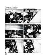
Страница 174: ...1 Left Side of Engine Compartment 4 Left Side of Engine Compartment ...

Страница 175: ...7 Left Side of Engine Compartment 10 Left Side f Engine Compartment 9 Below Cowl Cower 12 Leaf Side of Engine Compartment ...

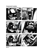
Страница 176: ...lilar Left Side Turn Srgsial 14 Behln lllght Right Similar I H I I I I H H H H H H Left HeacfigSii Lorn Beam Connector 2 GRY LetI Headlight High Beam r light Side f Eni mpartment 15 Behind Left Headlight Right Similar LD Uri 71 TlOl u ...

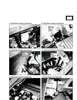
Страница 177: ...ol Unit Conn 2 GRY Connector 8 Connector 0 14 GRY GRY Right Front Wheel Speed Sensor Connector 2 ORN Horn 1 BLK 20 Right Sid f Engine Compartment 23 Bight Sid of Engine Compartment I 3ight Side of Engine Compartment 24 Behind Right Front Wheel Weii Windshield Washer Motor 2 BRN NAT ...

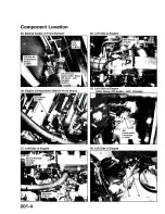
Страница 178: ... M i l A C Pressure Switch USA Base Or V dc Canada 2 GRY 26 Engine Compartment Below Front Beam mmmm 28 Lefi Sicis of Engine i l A P Sensor 3 BLK 19 USA Base GR Aud Canada Connector 27 LOC Y C l yy ie 30 Left Side of Engine TP Sensor Throttle Actuator ernator 8102 4 BLU ...

Страница 179: ...33 Middle of Engine 36 Middle of Engine ...

Страница 180: ...i engine G101 Behind Side of Transmission H H B H Back up I H H H H Light Switch I H H i 2 GRY J l Output Shaft Countershaft y Speed Sensor 3 BLK Rocker Arm Oil Control Solenoid VTEC Solenoid Valv Connector 1 GRY T103 42 Transmission Housing Connector ...

Страница 181: ...4 of Dash 46 Under Left Side of Dash i Unit 4 5 ImQQr IMl S i d 3J Dmh 5id of Dash I I M M PGM FI Main fl PGM FI Main I J H H H H Relay 2 mm Relay 1 I S BLtl I y B L U Behind H H H H H ...

Страница 182: ...49 Under Left Side of Dash 50 Under Left bid of Dash 51 Under Left Side of DasSi 52 Under Left Side of Dash 53 Under Left Side of Dash 54 Under Left Side of Dash ...

Страница 183: ...55 Behind Left Kick Panel 58 Behind Left Kick Panel 56 Behind Left Kick Panel iehind Left Kick Parse ...

Страница 184: ...63 Left of Steering Wheel 66 Steering Wheel Airbag Inflator Removed ...

Страница 185: ...ng Column Cower Immobilizer ignition Control Key Switch Unit Receiver 7 GRN 7 WHT Behind S i In Steering Colui i Connector B 3 GRY H H H H H l Switch H H H H 14 GRY HHiHHHB Behind 70 In Steering Column Oc c ir of Dash ag Cut off Indicator 4 GRN Audi Unit mm Connector B Connector A Antenna Lead 14 WHT 2Q LT BLU Connector ...

Страница 186: ......

Страница 187: ...79 Below Center of Console 82 Under Right Side of Dash 80 Under Middle of Dash Jnder Right Side of Dash 81 Under Right Side of Da ...

Страница 188: ...C Right s h 88 Under Right Srefe of Dash 1 inder Right Side of Dash H Q i M i n ...

Страница 189: ... Vir r Left Side of Floor Shut Valve 4 Behind Left Side Rear Trim Removable Hardtop Hi H H P CSC1 MO CR AJ id Rear 1 96 Behind Rlgl Sids Rom Mm Passenger s Door Switch 1 NAT Iff 1 ...

Страница 190: ...milar 101 Driver s Door Passenger s Similar Driver s Power Window liotor Connector 4 GRY LT GRN Driver s 2 GRY Passenger s Driver s Dc Speaker USA Base CR Audio Canada 2 GRY I Driver s Doorj Latch 3 GRY Behind Driver s Door Latch Connector B Behind Driver s Door Key Cylinder Switch L V J Behind ...

Страница 191: ...nder Driver s Roll Bar ResieOYabie Hardtop senger s Bom Convsrilbl Top Disable Switch Connector U S A CR C R Audio A C 2 GRY 105 Bet e r s Roll Bar Passenger s Similar 108 mm Driver s Seat Belt Tertsloner Behind I I Passenger s Door Lock Actuator I 2 GRY 1 Behind ISA Base CR Audio A C Canada PasssRgsfs Flight j Rear Speaker Passenger s Left Connector 3 BLK ...

Страница 192: ...ovable Hardtop 113 111 Right Side of Hardtop Removable Hardtop 114 lS d v 03C ...

Страница 193: ...113 UJ ojsr Passenger s Seat Connector A Connector onnector C 2 BLK YEL 2 BLK YEL 6 BLK YEL IIS Vj l Sl e of Trunk i BBBBfiBBBBl r Lo L riv Y T i Side of Trunk USA 14 WHT e of Trunk USA Base Canada ...

Страница 194: ...bly Right Similar 12S Middle of Trunk Lid Left Back t Light 2 GRY life Marker Taillight j Connector 3 3 GRY High Mount Brake Light Connector Turn Signal Light 2 GRY r r s Lie 0 3 SoSenoid Latch Switch Connector 3 GRY 123 Upper SiideSle of Try 126 Right Side of Trunk ...

Страница 195: ...127 Center of Rear Bumper I H H H H H H I H H H M H H H H I I License Plate Light 2 BRN NAT 128 Under Left Side f Dash TPSiS Control Unit 129 Under Right Sid f Dash Junction Connector 12 BLK ...

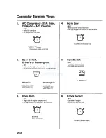
Страница 196: ... Driver s door switch output P a s s e n g e r s 1 LT GRN RED Passenger s door switch output 3 Horn High B L K Right side of engine compartment O n right engine compartment wire harness 1 BLU RED Horn control 4 Horn Low B L K Behind center of front bumper On right engine compartment wire harness 1 BLU RED Horn control 5 Horn Switch B L K Inside of steering wheel On cable reel assembly e r a 1 BRN ...

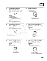
Страница 197: ...il Control Solenoid VTEC Solenoid Valve G R Y Right side of engine O n engine wire harness 1 Male GRN WHT Female GRN YEL Valve control VTS 10 Starter Solenoid B L K Left side of engine O n engine wire harness 11 1 BLK WHT Starter solenoid control A C Condenser Fan Motor USA Base CR Audio A C Canada G R Y Left side of engine compartment O n right engine compartment wire harness 1 BLK G201 2 Male BL...

Страница 198: ...re harness left branch or right branch Left 1 BLK G602 2 GRN BLK Back up light control input Right 1 BLK G602 2 GRN BLK Back up light control input 16 Back u _jgl Iwitch G R Y Left side of transmission O n engine wire harness 1 Male GRN BLK Female GRN YEL Switch output 2 Male GRN BLK Female YEL Fuse 5 17 Blower Motor NAT Under right side of dash On dashboard wire harness B right branch 1 BLU WHT H...

Страница 199: ...01 Convertible Top Motor Emergency Connector USA Base Canada G R Y Under right side of dash O n dashboard wire harness B right branch J EL_ 1 RED Left convertible top motor 2 LT GRN RED Right convertible top motor 23 Convertible Top Motor Left or Right USA Base Canada B R N Behind left or right side rear trim On rear wire harness left branch or right branch jTLJE 1 2 Left 1 RED Softtop close 2 Mal...

Страница 200: ...ashboard wire harness B right branch 1 BLU High beam cut relay power supply 2 RED YEL Fuse 45 28 ECT Sensor 1 B L K Rear of engine O n engine wire harness 1 RED WHT ECT1 2 GRN YEL Ground for ECM sensors SG2 circuit 29 ECT Sensor 2 B L K Left side of engine compartment O n left engine compartment wire harness 4 1 1 2 1 BLU ECT2 2 GRN Ground for ECM sensors SG3 circuit 30 EPS motor G R Y Engine comp...

Страница 201: ... n dashboard wire harness B right branch 34 Headlight Low Beam Le Right G R Y Behind left or right headlight On left or right engine compartment wire harness L e f t Right 1 BLK G501 2 M a l e R E D Female RED YEL Fuse 45 1 Male BLK Female LT GRN Sensor ground SCOM 2 Male BLK Female BRN Sensor output 1 BLK G501 2 Male RED Female RED WHT Fuse 43 35 High Mount Brake Light G R Y Middle of trunk lid O...

Страница 202: ...ower source for ECM circuit No 2 1 RED Control INJ2 2 YEL BLK Power source for ECM circuit No 3 1 BLU Control INJ3 2 YEL BLK Power source for ECM circuit No 4 1 YEL Control INJ4 2 YEL BLK Power source for ECM circuit 40 License Plate Light BRN NAT Center of rear bumper On rear wire harness right branch 1 RED BLK Illumination positive circuit 2 BLK G602 41 MES Connector Y E L Under left side of das...

Страница 203: ... compartment wire harness Left Front 1 BLK G301 2 RED BLK Illumination positive circuit Right Front 1 BLK G201 2 RED BLK Illumination positive circuit 46 Radiator Fan Motor G R Y Right side of engine compartment O n right engine compartment wire harness 47 1 BLK G201 2 Male BLU Female BLU BLK Radiator fan control input Rear Window Defogger Diode USA Base Canada BLK Left side of trunk O n rear wire...

Страница 204: ... RED Switch output 51 Security in line Fuse 1 Honda Accessory N A T Under left side of dash O n security system harness Honda Accessory WW 1 WHT Fuse 26 2 WHT BLU Security system 52 Security In line Fuse 2 Honda Accessory N A T Under left side of dash O n security system harness Honda Accessory at WW 1 YEL Fuse 5 2 YEL BLU Security system 53 Speaker Driver s Door or Passenger s Door USA Base CR Au...

Страница 205: ...de of engine compartment On left engine compartment wire harness rffh 1 2 BLU Tachometer signal 57 Trunk Lid Opener Switch NAT Behind rear of console O n rear wire harness left branch 1 BLK YEL Trunk lid opener switch output 2 WHT Fuse 26 58 Trunk Light G R Y Upper middle of trunk O n rear wire harness left branch 1 WHT BLU Fuse 24 2 BLU BLK Trunk lid position circuit Latch switch output 59 Turn S...

Страница 206: ...dio A C Canada G R Y Driver s or passenger s door O n driver s or passenger s door wire harness Left Male GRY RED Female BLK Audio Male GRN YEL Female RED Audio Right 1 Male LT GRN Female BLK Audio 2 Male GRN BLK Female RED Audio 13 Wheel Speed Sensor Left Front O R N Left side of engine compartment O n left engine compartment wire harness 1 Male BLU ORN Female RED FLW 2 Male BRN WHT Female WHT FL...

Страница 207: ...hind right front wheel well On right engine compartment wire harness 1 WHT BLK Washer motor control input 2 BLK G201 69 C351 G R Y Left side of engine compartment Connects EPS sub harness to left engine compartment wire harness 2 WHT RED Fuse 33 70 C452 G R Y Under right side of dash Connects dashboard wire harness B right branch to roof wire harness 1 GRN YEL Interior light 2 WHT BLU Fuse 24 71 C...

Страница 208: ...tion circuit 2 RED BLK Illumination positive circuit 3 BLK G602 74 CKP Sensor G R Y or BLK Front of engine O n C K P sensor sub harness 1 2 3 1 BLU Sensor output CKP 2 BRN YEL G101 3 YEL BLK Power source for ECM circuit 75 CMP Sensor B L K Rear of engine Engine wire harness 1 GRN Sensor output CMP 2 BRN YEL G101 3 YEL BLK Power source for ECM circuit 75 DRL Diode 2 USA WHT Under middle of dash O n...

Страница 209: ...t headlight On left or right engine compartment wire harness m Left Right 1 2 RED WHT High beam control 3 RED BLU High beam control 1 2 RED ORN High beam control 3 RED BLU High beam control 81 Ignition Coils B L U Middle of engine O n engine wire harness 1 No 1 1 WHT Coil control IGPLS1 2 BLK G101 3 BLK YEL Fuse 16 No 2 1 WHT GRN Coil control IGPLS2 2 BLK G101 3 BLK YEL Fuse 16 N o 3 1 WHT BLK Coi...

Страница 210: ...n 3 Male BLU Female GRN WHT Up Down control Right M a l e Y E L Female BLU WHT Left Right control Male BRN BRN Female RED BLU Common Male BLU Female GRN WHT Up Down control 85 86 Seat Belt Buckle Switch Driver s GRY BLU Under driver s seat On rear wire harness left branch 1 BLK G601 2 Male RED Female YEL BSDL 3 M a l e G R N Female LT GRN BSDH Seat Beit Buckle Switch Passenger s B L U Under passen...

Страница 211: ...ener control 2 BLK G601 3 Male BRN Female BLU BLK Trunk lid position circuit 91 C105 B L K Middle of engine Connects engine wire harness to C K P sensor sub harness 1 BLU PGM FI system 2 BRN YEL G101 3 YEL BLK Power source for ECM circuit 92 C601 G R Y Under driver s roll bar Connects rear wire harness left branch to hardtop sub harness removable hardtop 1 USA Base Canada LT GRN Convertable top 2 ...

Страница 212: ... GRN Driver s first inflator M a l e Y E L Female WHT Driver s first inflator 97 Airbag First and Second Inflators Passenger s Y E L Under right side of dash O n S R S main harness 1 M a l e Y E L Female BLU Passenger s first inflator 2 M a l e Y E L Female YEL or BLU Passenger s first inflator M a l e R E D Female LT BLU or BLU Passenger s second inflator Male RED Female LT GRN or BLU Passenger s...

Страница 213: ...ire harness 103 Ignition Coil Relay and A F Sensor Relay B L K Under left side of dash O n dashboard wire harness B right branch ra si mm Ignition Coil Relay 1 BLK YEL Fuse 16 2 GRN YEL Ignition system 3 GRN PGM FI main relay 1 control circuit 4 BLK YEL Fuse 16 Under dash A F Sensor Relay 1 WHT RED Fuse 15 2 WHT Power source for ECM sensors circuit 3 ORN AFSHTCR 4 YEL BLU Fuse 10 Under dash 104 Im...

Страница 214: ...onda Accessory BRN NAT Under driver s seat O n security system harness Honda Accessory 1 WHT Fuse 26 2 WHT Fuse 26 3 BLK YEL Trunk lid opener control 4 BLK ORN Relay control input 108 Power Window Motor Driver s GRY LT G R N Driver s door O n driver s door wire harness T l 2 3 4 Male BLU RED Female RED YEL Down Male BLU WHT Female RED BLK Up Male YEL Female BLU Window position pulse signal BLK Win...

Страница 215: ...Angle Sensor G R N In steering column cover O n dashboard wire harness B left branch i 1 1 2 1 3 1 4 i n 1 BLK G401 2 WHT CAN1 L 3 4 RED CAN1 H 5 BLK YEL Fuse 6 115 Windshield Wiper Motor G R Y Under left side of windshield On left engine compartment wire harness I w 1 BLU YEL Motor high control input 2 BLU Motor low control input 3 BLK G301 4 GRN BLK Fuse 8 5 BLU WHT PARK or RUN output 116 APP Se...

Страница 216: ...Switch NAT Left of steering wheel On dashboard wire harness A 6 7 1 LT GRN Switch output 2 RED BLK Dash and console lights 3 RED Dash and console lights 4 5 BLK G501 6 BLK YEL Fuse 6 120 Intermittent Wiper Relay BRN NAT Left side of engine compartment O n left engine compartment wire harness 2 4 5 6 1 BLK G301 2 GRN RED Intermittent control output or RUN to Park output 3 GRN BLK Fuse 8 4 BLU WHT R...

Страница 217: ...ly Honda Accessory BRN NAT Under driver s seat O n security system harness Honda Accessory T O T J 1 2 L 3 4 5 6 1 WHT Fuse 26 2 YEL GRN Driver s door unlock control 3 WHT Fuse 26 4 YEL WHT Unlock signal 5 6 YEL RED Relay control input 125 WSA Off Switch N A T Right of steering wheel O n dashboard wire harness A 1 2 3 4 5 6 r 1 WHT VSA system 2 RED BLK Illumination positive circuit 3 RED Illuminat...

Страница 218: ...wire harness 1 EBSi 2 3 4 5 6 U U Male PNK Female PNK or BLU SRS BLK G501 BLU SRS Male BLK YEL Female BLK YEL or BLU Gauges and Indicators Male BRN Female BRN or BLU Service check signal circuit Male GRY Female GRY or BLU Offboard diagnosis signal circuit 131 Air Mix Control Motor G R N Under right side of dash O n dashboard wire harness B right branch m TP i n 1 PNK BLU M HOT 2 PNK M COOL 3 PNK B...

Страница 219: ... RED Fuse 52 7 USA Base Canada GRY Fuse 55 8 RED BLU R high beam control BRN Under right side of dash Connects right engine compartment wire harness to dashboard wire harness B right branch JpESi 1 1 2 I L l 4 5 6 7 I WHT BLU Fuse 50 VSA BLU WHT Blower motor relay WHT Fuse 42 Ignition switch WHT RED Fuse 48 VSA WHT BLK Fuse 51 to fuses 17 and 18 YEL Fuse 54 to fuses 22 27 WHT Under left side of da...

Страница 220: ... 9 10 1 GRN RED Left hazard control output 2 GRN YEL Right hazard control output 3 BLK RED Turn signal hazard relay power 4 5 RED BLU Fuse 7 6 WHT BLK Fuse 49 7 8 RED BLK Dash and console lights 9 RED Dash and console lights 10 GRN WHT Hazard request output 141 Power Mirror Switch G R N Driver s door O n driver s door wire harness TP 11 12 13 14 15 16 17 18 19 11 I 1 2 3 BLU WHT Right mirror left ...

Страница 221: ... system 12 GRN WHT VSA system 145 C507 Junction Connector B L U Under right side of dash O n dashboard wire harness A 1 2 3 4 5 6 7 8 9 10 11 12 1 BLU Gauges and Indicators I 2 BLU Gauges and Indicators j I 3 BLU Gauges and Indicators I 4 BLU Gauges and Indicators J f 5 GRN Fans 1 6 GRN Fans J j 1 7 BRN Service check signal circuit 8 BRN Service check signal circuit 9 BRN Service check signal circ...

Страница 222: ... Audio system 14 BLK Audio system 148 D R I itrol Unit W H T G R Y Under left side of dash On dashboard wire harness B right branch RED WHT Headlights USA WHT DRL sub control unit Canada RED BLU Fuse 27 RED YEL Fuse 45 BLK G402 RED WHT Fuse 43 GRN WHT Parking brake position circuit BLK G402 8 BLU RED High beam cut relay 9 Canada BLU WHT DRL indicator control 10 Canada RED BLU High beam headlights ...

Страница 223: ...ntrol input 8 RED YEL Headlights 151 Wiper Washer Switch GRY In steering column cover O n dashboard wire harness B left branch 1 2 3 4 5 6 7 8 9 10 11 12 13 14 BLK G401 BLU YEL HIGH motor control output WHT BLK Washer request output 9 10 11 BLU LOW motor control output 12 GRN RED Intermittent control input or RUN to PARK input 13 BLU BLK Intermittent wiper request 14 BLK WHT Fuse 12 1 5 2 C301 G R...

Страница 224: ...e harness A 1 2 n 3 4 5 9 j10 1 1 1 1121 3 j l 4 J 15 16 1 Male BLK YEL Female GRN YEL Ignition system 2 USA Base CR Audio A C Canada Male BLK RED Female BLU RED HVAC 3 BLK WHT Starting system 4 YEL BLK Power source for ECM circuit 5 BLK YEL Fuse 6 6 Male WHT BLK Female WHT Power source for ECM sensors circuit 7 Male WHT BLU Female Not used 8 BLU WHT Vehicle speed sensor signal 2 circuit 9 M a l e...

Страница 225: ...A Base CR Audio A C Canada WHT BLU Fuse 22 Audio system 16 WHT RED Fuse 25 160 C451 LT B L U Under right side of dash Connects dashboard wire harness B right branch to dashboard wire harness A 1 2 n 3 4 5 6 l7 h 9 I10 I11 12 1 3 1 4 1 5 16 1 BLU BLK Wiper washer 2 WHT Fuse 26 3 GRN WHT Fuse 17 4 BLU ORN Intermittent wiper circuit 5 GRN YEL Ceiling lights spotlights or keyless 6 PNK BLK HVAC 7 PNK ...

Страница 226: ... 12 13 14 15 16 17 18 19 J 1 N R 1 YEL BLK Power source for ECM circuit 2 YEL BLK Power source for ECM circuit 3 YEL BLK Power source for ECM circuit 4 YEL BLK Power source for ECM circuit 5 YEL BLK Power source for ECM circuit 6 YEL BLK Power source for ECM circuit 7 YEL BLK Power source for ECM circuit 8 YEL BLK Power source for ECM circuit 9 YEL BLK Power source for ECM circuit J Terminals grou...

Страница 227: ...ks keyless entry 11 YEL Power door locks keyless entry 12 YEL BLK Power door locks keyless entry 13 RED BLU Right mirror common 14 BLK G501 15 BLU WHT Convertible top or power windows 16 BLU RED Convertible top or power windows 17 GRN BLK Fuse 8 power windows 18 RED WHT Power windows 19 USA Base CR Audio A C Canada GRY RED Audio system 20 167 TPMS Control Unit G R Y Under left side of dash O n das...

Страница 228: ... Canada positive circuit 14 GRN YEL RED WHT 3 GRY Turn signal lights Convertible top DLC and MIL circuits 15 GRN RED 17 USA Base Canada 4 LT GRN RED Turn signal lights RED Convertible top Cruise control 16 GRN Wiper washer 18 USA Base Canada 5 LT GRN Cruise control 17 GRN WHT Parking RED BLU 6 BLU WHT DRL brake position circuit Convertible top 7 GRN YEL 18 YEL BLK Fuse 1 9 19 GRN YEL Fuel supply s...

Страница 229: ...stem 28 WHT Audio system 172 Heater Control Panel G R N Right of steering wheel O n dashboard wire harness A 1 2 3 4 5 6 7 X T 8 9 10 11 12 13 14 15 16 17 18 19 20 21 24 25 26 27 28 29 30 1 2 3 4 5 6 7 8 9 10 11 12 13 14 15 16 17 18 19 20 21 22 23 24 25 26 27 28 29 30 PNK Air mix control M COOL output PNK BLU Air mix control M HOT output YEL BLU Mode control M DEF output YEL RED Mode control M VEN...

Страница 230: ... 34 GRN BLK FR B 11 RED CAN1 H 35 GRN ACT 12 36 YEL RED RL B 13 PNK WL EBD 37 GRY RED RL GND 14 38 15 WHT CAN1 L 39 16 BLK G303 40 17 PNK BLK ACT 41 18 42 BLU YEL RR GND 19 43 GRN WHT RR B 20 44 BLU RED ABS 21 45 BLU ORN FL B 22 46 BRN WHT FL GND 23 47 BLK G303 24 174 ACC Cut Relay and IG2 Relay G R Y Under left side of dash O n dashboard wire harness B right branch JUL ACC Cut Relay 1 WHT RED Acc...

Страница 231: ...RR 16 GRY RED LR 17 LT GRN RF 18 GRY RED LF 19 RED ILL 20 BLK Ground Connector B Honda Accessory Canada LT BLU C D changer accessory B U S cable 1 2 3 4 5 6 7 8 9 10 11 12 13 14 BLK Audio system RED Audio system BRN Audio system BLU Audio system 8 BLK Audio system 9 WHT Audio system 10 BLK Audio system 11 12 YEL Audio system 13 GRN Audio system 14 Connector B USA W H T O n dashboard wire harness A...

Страница 232: ...L On main S R S wire harness rJ 3 4 1 M a l e Y E L Female GRN or BLU Driver s second inflator 2 Male BLK Female PUR or BLU Driver s second inflator 3 Male GRN Female LT BLU or BLU Driver s first inflator 4 Male WHT Female BRN or BLU Driver s first inflator Connector B G R Y On dashboard wire harness B left branch Male LT GRN BLK Female BLU Cruise resume sw Male LT GRN RED Female RED Cruise set sw...

Страница 233: ... G402 14 BLU BLK Fuse 18 Connector B O n dashboard wire harness A 02 r i IT 3 4 1 5 H8 J 10 1 Y E L Fuse 5 2 BLU ORN Driver s window down control output 3 RED BLU Passenger s window up 4 RED Passenger s window down 5 LT GRN Hardtop CONNECTED signal option 6 WHT BLK Vehicle speed sensor signal 1 circuit vehicle speed input 7 BLU WHT Passenger s window down request input 8 BLU RED Passenger s window...

Страница 234: ...17 RED YEL IAT 6 GRN YEL VTS 18 WHT GRN ALTC 7 19 GRN SEFD 8 RED WHT ECT 1 20 BLU SEDF 9 21 YEL BLU PCS 10 WHT BLU ALTL 22 11 BLU BLK VTPSW 23 12 24 Connector D W H T O n dashboard wire harness A 1 r 1 2 3 4 5 6 7 8 9 10 11 12 13 14 15 16 17 1 LT GRN RED CCSETSW 2 3 4 LT GRN CCMSW 5 6 7 LT GRN BLK CCSRESSW 8 GRY BKSWNC 9 PNK CCCLSW 10 11 12 13 14 15 BRN ETCSRLY 16 17 Connector E W H T On dashboard...

Страница 235: ...d wire harness A Connector A GRN 1 2 3 4 5 6 7 8 9 10 11 12 13 14 15 E B 18 19 20 21 22 1 YEL Fuse 5 2 BLU WHT DRL indicator 3 WHT RED Fuse 25 4 PNK Immobilizer indicator 5 BLK WHT Door open output 6 7 RED YEL Fuse 45 8 RED BLK Illumination positive circuit Dash and console lights 9 YEL Fuse 5 10 WHT RED Fuse 25 11 GRY K LINE 12 BLU BLK Trunk indicator 13 LT GRN RED Passenger s door switch input 1...

Страница 236: ...input 17 BLU BLK Intermittent wiper request input 18 WHT BLK Washer request input 19 PNK SRS indicator circuit 20 BLU RED VSA indicator circuit input 21 YEL BLU EPS indicator 22 PNK Outside air temperature sensor 23 GRN WHT Parking brake switch input 24 GRN RED Brake system indicator input 25 PNK VSA 26 YEL MIL control 27 YEL RED Engine oil pressure switch input 28 BLK Outside air temperature sens...

Страница 237: ...C 185 PGM FI Main Relays 1 and 2 B L U Under left side of dash O n dashboard wire harness B right branch 0 PGM FI Main Relay 1 1 WHT GRN Fuse 46 2 YEL BLK Power source for ECM circuit 3 GRN MRLY 4 WHT GRN Fuse 46 PGM FI Main Relay 2 1 BLK YEL Fuse 2 2 YEL GRN Fuel pump 3 GRN YEL Fuel pump control 4 5 YEL BLK Power source for ECM circuit 1 2 3 BLK YEL Fuse 2 4 5 GRN ODUS 6 BLK G601 ...

Страница 238: ...ront impact sensor 17 BLK YEL or BLU VA 18 PNK or BLU VB 19 20 21 BLK YEL or BLU SRS 22 GRN or BLK or BLU G801 23 GRN or BLK or BLU G801 24 GRY or BLU K LINE 25 26 27 RED or BRN Left front impact sensor 28 GRN or BLU Right front impact sensor Connector B 1 I 2 3 4 5 6 7 8 9 10 1 13 14 15 16 17 18 19 20 21 22 23 24 25 26 27 28 1 RED or BLU Seat belt tensioner driver s 2 BRN or BLU Seat belt tension...

Страница 239: ... of dash On dashboard wire harness B left branch Accessory Power Socket Relay 1 WHT Relay output 2 BLU Fuse 53 3 BLK G401 4 WHT RED Fuse 9 Throttle Actuator Control Module Relay 1 YEL GRN Electronic throttle control system 2 BLU WHT Fuse 14 3 BRN Electronic throttle control system 4 YEL GRN Fuse 11 ...

Страница 240: ...ion Fuse 2 Female BLU or BLK YEL SRS unit Ignition input Connector B Male In under dash fuse relay box Female BRN Connects under dash fuse relay box to ignition switch lead 1 WHT Fuse 42 Battery output 2 ORN Ignition switch ON output 3 BLK RED Ignition switch ON output 4 Male Internal connection Busbar Fuses 1 through 7 Female BLK YEL Ignition switch ON output 5 WHT RED Ignition switch ACC or ON o...

Страница 241: ...ay 1 BLK RED 2 GRN WHT Turn signal hazard Ignition ON or hazard power supply switch ON input 3 BLK G401 Fuses 1 Internal connection 10A internal connection 2 Internal connection 15A internal connection 3 BLK WHT 7 5A internal connection 4 5 YEL 7 5A internal connection 6 BLK YEL 15A internal connection 7 RED BLU 7 5A internal connection 8 GRN BLK 20A BLK YEL 9 YEL RED 10A WHT RED 10 YEL BLU 7 5A Y...

Страница 242: ...13 14 15 16 17 WHT GRN Fuse 46 PGM FI 18 Connector B B R N E E 1 WHT BLU Fuse 50 2 GRY Fuse 55 3 GRY RED Fuse 52 4 WHT BLK Fuse 49 Hazard warning lights 5 WHT GRN Fuse 47 6 WHT BLK Fuse 51 7 YEL Fuse 54 Connector C B R N n q h 2 1 BLU WHT HVAC 2 WHT Fuse 42 3 BLU Fuse 53 Connector D LT G R N 1 2 3 1 1 4 5 6 7 8 1 0 1 1 11 2 13 14 15 16 1 BLK YEL Fuse 20 2 YEL Fuse 59 3 BLU BLK Fans 4 USA Base CR A...

Страница 243: ...R 14 GRN L Connector B BLK On X M antenna Honda Accessory 1 BLK Terrestrial signal antenna 2 BLK Satellite signal antenna 191 C51 Honda Accessory G R Y Under left side of dash Connects hood switch harness Honda Accessory to security system harness Honda Accessory 1 YEL RED Security system 2 192 C650 G R Y Under driver s seat Connects rear wire harness left branch to driver s seat position sensor s...

Страница 244: ...ght side of engine compartment Body ground via battery ground cable Battery negative terminal S t a r t e r C a b l e Ref C o n n e c t o r or Terminal Cavities Color Location C o n n e c t s to Notes 5 6 9 11 G3 T7 T2 T3 Left side of engine compartment Left side of engine compartment Left side of engine Left side of engine Body ground via starter cable Auxiliary under hood fuse box Starter motor ...

Страница 245: ......

Страница 246: ... Behind left kick panel 16 ECM connector B 24 WHT Behind left kick panel 17 C103 13 WHT Behind left kick panel Dashboard wire harness A see page 203 12 18 C104 Junction connector 20 PNK Behind left kick panel 19 Injector No 4 2 BLU Middle of engine 20 Starter solenoid 1 BLK Left side of engine 21 TP sensor throttle actuator 6 BLK Left side of engine 22 MAP sensor 3 BLK Left side of engine 23 A C c...

Страница 247: ...I J CKP Sensor Sub harness ...

Страница 248: ...t side of engine compartment 16 ELD unit see page 6 1 3 GRY Right side of engine compartment Under hood fuse relay box 17 EPS control unit connector A 2 GRY Right side of engine compartment 18 Windshield washer motor 2 BRN Behind right front wheel well NAT 19 EPS control unit connector B 14 GRY Right side of engine compartment 20 Right side turn signal light 2 BRN Behind right fender NAT 21 C204 2...

Страница 249: ......

Страница 250: ...tment wire harness 12 Left side turn signal light 2 BRN Behind left fender NAT 13 Intermittent wiper relay 6 BRN Left side of engine compartment NAT 14 Test tachometer connector 2 BLK Left side of engine compartment 15 Brake fluid level switch 2 GRY Left side of engine compartment 16 C301 14 GRY Under left side of dash Dashboard wire harness B left branch see page 203 8 17 C304 8 WHT Under left si...

Страница 251: ......

Страница 252: ...gh beam cut relay 4 GRY Under left side of dash 11 Rear window defogger relay 5 GRY Under left side of dash 12 Clutch pedal position switch 2 NAT Under left side of dash 13 Clutch interlock switch 2 YEL Under left side of dash 14 C301 14 GRY Under left side of dash Left engine compartment wire harness see page 203 6 15 C302 16 Under left side of dash Left engine compartment wire LT BLU harness see...

Страница 253: ......

Страница 254: ...ash Dashboard wire harness A see page 203 12 16 C203 7 BRN Under right side of dash Right engine compartment wire harness see page 203 4 17 C201 16 LT BLU Under right side of dash Right engine compartment wire harness see page 203 4 18 C451 16 LT BLU Under right side of dash Dashboard wire harness A see page 203 12 19 Imoes unit 5 GRN Under right side of dash 20 G402 Under right side of dash Body ...

Страница 255: ... Continues to left ...

Страница 256: ...2 GRN Behind gauge assembly 18 Heater control panel 30 GRN Right of steering wheel 19 Passenger s air bag cut off indicator 4 GRN Center of dash 20 Audio unit connector A 20 LT BLU Behind audio unit 2 21 C551 2 GRY Behind lower center of dash Antenna amplifier sub harness see page 203 16 2 22 C453 12 WHT Under right side of dash Dashboard wire harness B right branch see page 203 10 23 Convertible ...

Страница 257: ......

Страница 258: ...de of trunk Rear window defogger sub harness softtop see page 203 21 Softtop 14 Left brake side marker tailiight 3 GRY Behind left taillight assembly 15 Left rear turn signal light 2 GRY Behind left taillight assembly 16 Left back up light 2 GRY Behind left taillight assembly 17 Trunk lid opener solenoid latch switch 3 GRY Middle of trunk lid 18 High mount brake light 2 GRY Middle of trunk lid 19 ...

Страница 259: ...motor 2 BRN Behind right side rear trim 2 6 Accessory power socket 2 BLK Behind rear of console 7 Right rear wheel speed sensor 2 ORN Right side of trunk 8 Passenger s right rear speaker 2 BLK Under passenger s roll bar 1 9 Right brake side marker taillight 3 GRY Behind right taillight assembly 10 Right rear turn signal light 2 GRY Behind right taillight assembly 11 Right back up light 2 GRY Behin...

Страница 260: ...l trim Under right side of dash Dashboard wire harness B right branch see page 203 10 Antenna Amplifier Sub harness USA Base CR Audio A C Canada Ref C o n n e c t o r or Terminal Cavities Color Location C o n n e c t s to Notes 3 4 C551 AM FM antenna amplifier 2 GRY 2 GRY Behind lower center of dash Right side of trunk Dashboard wire harness A see page 203 12 Roof Wire Harness ...

Страница 261: ... side of dash Under left side of dash In steering column cover Behind lower center of dash Behind lower center of dash Under right side of dash Under right side of dash Behind passenger s roll bar Behind rear of console Behind driver s roll bar Behind lower center of dash Under left side of dash Dashboard wire harness A see page 203 12 Right engine compartment wire harness see page 203 4 Rear wire...

Страница 262: ...r s door speaker 2 GRY Driver s door 1 4 Power window master switch 14 GRY Driver s door 5 Power mirror switch 10 GRN Driver s door 6 Driver s power window motor 4 GRY LT GRN Driver s door 7 8 Driver s door key cylinder switch Driver s door latch connector B 2 GRY 2 GRY Driver s door Driver s door 9 Driver s door latch connector A 3 GRY Driver s door 10 Left tweeter 2 GRY Driver s door 1 1 USA Bas...

Страница 263: ...re harness A see page 203 12 2 Right power mirror 3 GRY Passenger s door 3 Passenger s door speaker 2 GRY Passenger s door 1 4 Passenger s power window switch 6 GRN Passenger s door 5 Passenger s power window motor 2 GRY Passenger s door 6 Passenger s door lock actuator 2 GRY Passenger s door 7 Right tweeter 2 GRY Passenger s door 1 1 USA Base CR Audio A C Canada ...

Страница 264: ... a b l e Hardtop CR CR A u d i o A C Ref C o n n e c t o r r T e r m i n a l Cavities Color Location C o n n e c t s to Notes 4 6 8 Rear window defogger connector A G901 C901 1 NAT 3 BLK Left side of hardtop Left side of hardtop Behind left side rear trim Body ground via hardtop wire harness Hardtop sub harness see this page Rear W i n d o w Defogger Ground Wire Removable Hardtop CR CR Audio A C R...

Страница 265: ...tor or Terminal Cavities Color Location C o n n e c t s to Notes 1 Rear window defogger connector A 1 BLK Left side of softtop 2 Rear window defogger connector B 1 BLK Left side of softtop 3 C602 2 BRN Left side of trunk Rear wire harness left branch see page 203 14 3 ...

Страница 266: ...o install a pigtail terminal a short length of wire with a factory crimped terminal on it Refer to HOW TO INSTALL PIGTAIL TERMINALS Removing the Terminal Use the tools from Pin Tool Set First check the connector that you are about to repair If it has a secondary terminal lock go to Connectors With a Secondary Lock A secondary lock found on most connectors on some models is an additional locking de...

Страница 267: ... the tool under the terminal and lift up EXAMPLE C 1 Remove the secondary lock Carefully pry the secondary lock out of the connector 2 Remove the terminal from the female half Female Terminal Half Push the wire into the connector to relieve the tension on the primary lock PIN TOOL G Pull the terminal out of the connector Insert the tool at the middle of the terminal and lift up on the primary lock...

Страница 268: ...l the terminal out of the connector PIN TOOL A 3 Go to HOW TO INSTALL NEW TERMINALS EXAMPLE E 1 Remove the secondary locks Gently pry up on the back of the secondary terminal lock Roll the secondary lock up so the lugs of trie lock are free of the connector 2 Remove the terminal same procedure for male and female Push the wire into the connector to relieve the tension o n the primary lock Insert t...

Страница 269: ...e tool below the terminal Push down on the tool to lift the primary lock Pull the terminal out of the connector PIN TOOL F Connectors Without a Secondary Lock All examples are shown with the connector lock facing up The illustrations are examples of connector terminals without a secondary lock however the connector you are repairing may vary in size and shape EXAMPLE A 1 Remove the terminal Push t...

Страница 270: ...cess slot above the terminal Pull the terminal out of the connector Twist it 90 to release the lock Slide the tool into the primary lock EXAMPLE E 1 Remove the terminal Push the wire into the connector to relieve the tension on the primary lock 0 TOOLE Pull the terminal out of the connector Lift up on the tool to release the primary lock Insert the tool below the terminal 2 Go to HOW TO INSTALL NE...

Страница 271: ...isted on the inside lid of the terminal repair kit Replacement terminals are available through your parts department using normal parts ordering procedures 2 Depending on the size of the wire you are repairing use the proper size slot in the crimping tool 3 Strip the insulation off the end of the wire so the wire fits in the new terminal as shown If the wire has a wire seal replace it with a new o...

Страница 272: ...pe Keep a circle shape Ends touching 8 Inspect the quality of the wire crimp If it has any of the following NO GOOD crimps cut it off and start over Wire should be visible here J 1 GOOD Wire crimp is crimping on the insulation not wire NO GOOD Loose strands of wire NO GOOD Wire crimp not crimped evenly NO GOOD GOOD Crimped edges should be even NO GOOD Poor crimping If one side sticks out more the ...

Страница 273: ...he pigtail terminal into the connector cavity push it in until it locks in place NEW PIGTAIL ORIGINAL WIRE 6 Lay the pigtail and the original wire side by side and cut off both ends at once If you are making more than one splice do not cut each pigtail at the same location the resulting lump of splice connectors would interfere with rewrapping the harness Instead cut the first pigtail close enough...

Страница 274: ...til the jaws touch and hold it at that position until the ratchet clicks again FLARE CRIMPER JAWS SPLICE CONNECTOR BARE WIRE 10 Crimp the other wire in the same way into the other end of the splice connector 11 After crimping gently pull on the wires in the opposite directions to make sure they are secure in the connector 12 Separate the other wires in the harness from the repaired wire s and shie...

Страница 275: ...fit can cause a number of intermittent problems in electrical circuits By using the Terminal Inspection Feeler Tool Set you can inspect the terminal fit between the two matching connectors without removing the terminals from the connector body 1 Find the terminal tool that best matches the male terminal in the mating connector 2 Insert the terminal tool into the female terminal and then remove the...

Страница 276: ......

Страница 277: ......

Страница 278: ......

Страница 279: ......

Страница 280: ... Portions of materials contained herein have been reprinted under license from America Honda Motor Co Inc License Agreement AH220 ...

Отзывы: