7 |
P a g e
Rev 05/2019
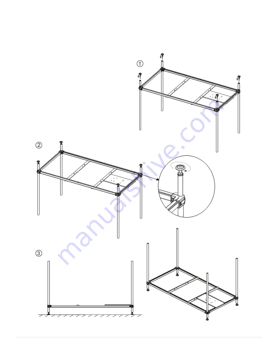
Step 2:
a.
Turn the frame upside down.
b.
Take 4 adjustable feet and install them in the end of supporting pole A at the bottom of the frame (figure 1).
c.
Adjust the feet so that the bottom frame is leveled.
Страница 1: ...1 P a g e Rev 05 2019 NEPTUNE Model HY42 Installation Manual Note You must read all installation operation instructions prior to assembly and use of this unit...
Страница 2: ...3 Plumbing Requirements 4 Electrical Information 4 Packing List 5 Assembly Instructions 6 14 Parts Request 15 Warranty Information 16 Note We keep improving and upgrading the product All rights are r...
Страница 3: ...Note Tub needs to be leveled in its final resting position mark the placement then pull tub out and begin assembly of wall panels It is advised to have tub onsite before preparing drain location 6 All...
Страница 4: ...included ELECTRICAL INFORMATION 1 Air jet motor with heater 110 volt 2 Whirlpool system 110 volt optional inline heater to be installed into whirlpool system s electrical no additional outlet require...
Страница 5: ...5 P a g e Rev 05 2019 PACKING LIST Check the parts in the box against the packing list if any parts are missing contact the supplier...
Страница 6: ...SEMBLY INSTRUCTIONS Step 1 a Place the bottom frame on the ground b Insert four supporting poles A in the corner holes of the frame figure 1 2 c Align the screw holes and secure the support poles righ...
Страница 7: ...ev 05 2019 Step 2 a Turn the frame upside down b Take 4 adjustable feet and install them in the end of supporting pole A at the bottom of the frame figure 1 c Adjust the feet so that the bottom frame...
Страница 8: ...to the bottom frame b Adjust the height of the feet and secure with hexagon nuts Make sure the bottom frame is leveled and all feet are supporting the frame figure 2 3 Failure to do so will compromis...
Страница 9: ...he middle frame slide the frame on the supporting poles as shown in figure 1 b Align and secure the four supporting poles A with screws on the corner connectors as shown in figure 2 c Align the rest o...
Страница 10: ...10 P a g e Rev 05 2019 Step 5 a Install supporting pole B on the middle frame as shown in figure 1 through 3...
Страница 11: ...ub MUST be secured to the back wall and the floor to prevent tipping upon entering and exiting the tub c It s advised to set the frame to the position to determine the best way to secure the frame Aft...
Страница 12: ...osition the corner poles to connect to the 4 corner connection as shown in figure 1 and 2 b Place the U channels on the bottom of the tub body into the support beams on the middle supporting frame as...
Страница 13: ...able See image below b Install side skirts if applicable Figure 1 Note make sure the power and water supplies are connected before moving the tub into its final place Tub frame MUST be secured to the...
Страница 14: ...b Connect the drain as shown in figure 2 Note The flexible drain hose that is included with this unit is for installation into an open floor drain only Substituting the existing drain shoe for a diff...
Страница 15: ...15 P a g e Rev 05 2019 To expedite a Parts Request please visit homewardbath com support If you would like additional assistance Call 866 783 2661...
Страница 16: ...NFORMATION REGISTRATION Please visit our website homewardbath com warranty registration Registration must be completed within 45 days of receipt to be valid A full description of the warranty is avail...