Assembly Instructions /
6 8
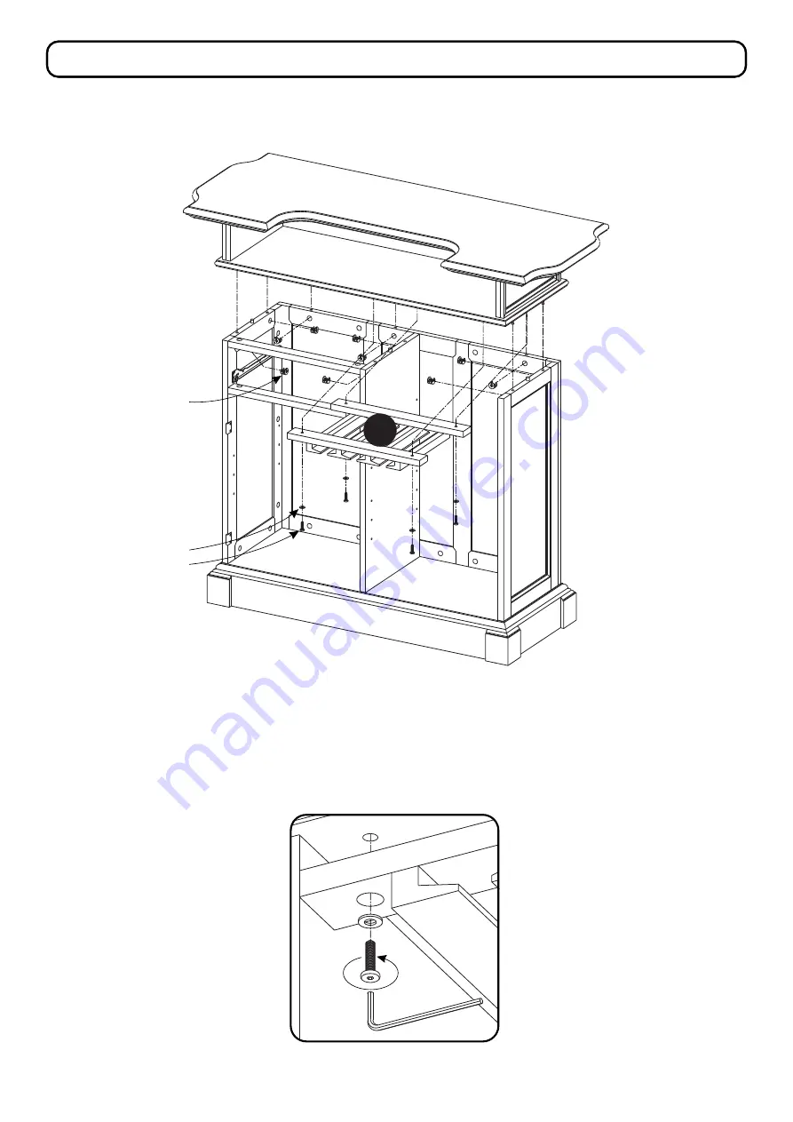
STEP 9
Attach unit from Step 2 to unit with Cam Locks.
Attach Glass Holder (E) to unit with Head Cap Bolts and Flat Washers.
(See Figure )
5
E
Cam Lock
Washer
Head Cap Bolt
Figure 5
Страница 1: ...her damage Carefully and strictly follow these assembly instructions to ensure a completed product as designed Do not use power tools above 8 volts to assemble Part List E Glass Holder 1 pc A Top 1 pc...
Страница 2: ...cs 500 992 3 Bar IMPORTANT Carefully remove all the parts from the carton and place them individually on a soft cloth to prevent scratches or other damage Carefully and strictly follow these assembly...
Страница 3: ...le Panel L with Wood Screws into pre drilled holes See Figure 2 Figure 2 Do put Cam Lock Screws not in these holes Wood Screw Magnet H A B M H I K L Figure 1 IMPORTANT Use a soft cloth between these p...
Страница 4: ...h Attach Side Panels D and Front Panel C to Top A with Cam Locks See Figure 3 Attach Sub Top B to unit with Head Cap Bolts and Flat Washers See Figure 4 H I STEP 3 Attach Front Panels H to Front Panel...
Страница 5: ...P 4 Attach Side Panels J and K to unit from Step 3 with Cam Locks Attach Base M to unit with Cam Locks STEP 5 Attach Front Rails F to unit with Cam Locks Attach Middle Panel L to unit with Cam Locks C...
Страница 6: ...8 Attach Knob with Machine Screw STEP 6 Attach Drawer Front R1 and Drawer Back R2 to Drawer Side R3 with Wood Screws long STEP 7 Slide Drawer Bottom R5 into groove Attach Drawer Side R4 to unit with...
Страница 7: ...Assembly Instructions 6 8 STEP 9 Attach unit from Step 2 to unit with Cam Locks Attach Glass Holder E to unit with Head Cap Bolts and Flat Washers See Figure 5 E Cam Lock Washer Head Cap Bolt Figure 5...
Страница 8: ...unit by sliding door hinges into side panel hinges See Figure 7 Attach Knob to Door N with Machine Screw See Figure 8 Slide Drawer R into position Level unit by adjusting the adjustable levelers on bo...
Страница 9: ...apered Wood Screws into pre drilled holes See Figure 11 Attach Foot Rest Q to Foot Rest Supports P with Head Cap Bolts short leaving same amount of Foot Rest Q protruding on outside of outer Foot Rest...
Страница 10: ...ING Do not place in direct sunlight PREVENT FADING with a soft cloth moistened in lukewarm soap and water Buff with a dry clean cloth CLEAN homestyles will provide replacements free of charge for miss...