ZIR000 Instructions, Release 1.1
P/D 110805
HomePro
by ADVANCED CONTROL TECHNOLOGIES, INC.
0685-01
2
Mounting the Detector
1. Hold the provided mounting bracket in the location you want to mount the ZIR000. Mark the wall (or
ceiling) where the two screw holes will be drilled.
2. Complete the following two steps if mounting in drywall, if there is no stud (or joist).
a. Drill a pilot hole of 11/64”.
b. Tap the provided wall anchors into the wall (or ceiling).
3. Screw the mounting bracket to the wall (or ceiling) with the screws provided.
4. Snap the ZIR000 onto the bracket.
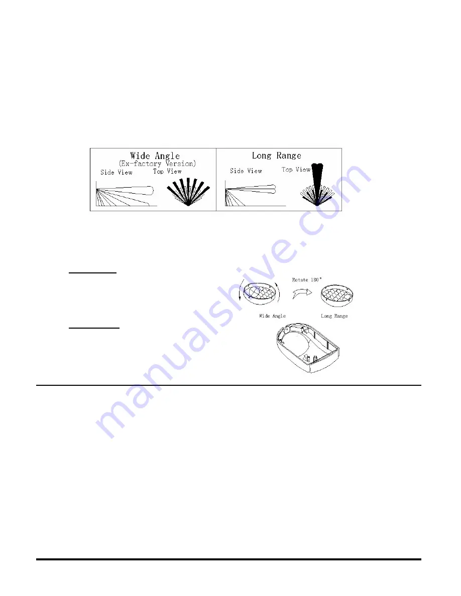
5. Adjust the vertical pattern angle per figure 2, if desired.
Fig 2
LENS can be adjusted to suit your needs by simply rotating the angle of the lens 180
o
to change from wide
angle version (Default setting) to long range version if required. The number of detection zones will change
between wide angle and long range.
WIDE ANGLE
(Default Setting)
Angle: 105
o
x 110
o
Distance: 39 feet (12 meters)
Zone Number: 64
LONG RANGE
(Default S 180
o
)
Angle: 5
o
x 5
o
Distance: 46 feet (14 meters)
Zone Number: 8
ADD TO NETWORK
To include or exclude the ZIR000 from the Z-Wave network, press the brown button marked “button” (inside)
when prompted by a Z-Wave controller. For ZIR000 to work properly over longer distances (i.e. communcate
via more nodes), add it to the network after you have added all other non-battery operated devices. Now
replace the cover and screw. The ZIR000 will stay “awake” for ten minutes when power is first applied to
allow time for configuration.
The ZIR000 can be configured to operate in 1 of 3 modes.
Those modes are:
•
Lighting Mode (factory default)
•
Alarm Mode
•
Sensor Mode
To change the mode of operation:
For Lighting Mode
: Send a value of 0 to Configuration Parameter #17.
For Alarm Mode
: Send a value of 1 to Configuration Parameter #17.
For Sensor Mode
: Send a value of 2 to Configuration Parameter # 17.
Refer to your controller instructions on how to set Configuration parameters.


