


3
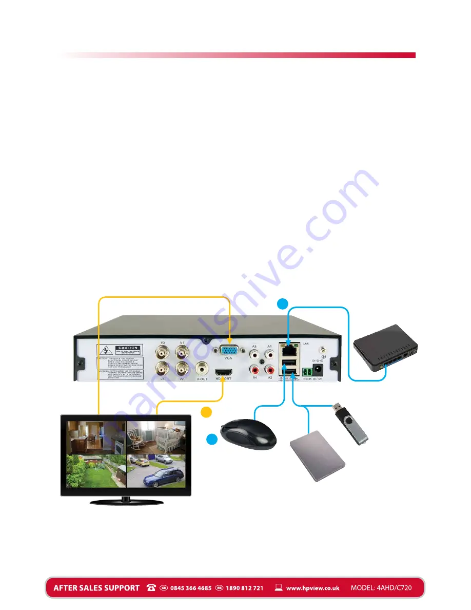
Video & Data Connections
3
Router/Wireless
access point
Display/Monitor
Mouse [E] - USB 2.0
connection
USB storage device -
USB 2.0 connection
Fig. 3 Video & Data Connections
Connecting to your home network see Fig. 3 below
Plug the RJ45 Ethernet cable supplied [G] into the LAN port [6 on Fig. 1] on the DVR and the
other end into a spare port on your router or wireless access point.
Connecting the mouse see Fig. 3 below
Connect the mouse to the upper USB 2.0 port of the two available marked USB 1 [4 on Fig. 1].
Alternatively you can connect the mouse to the USB port on the bottom right of the front panel.
Use one or the other to connect the mouse.
Connecting the DVR to a Display see Fig. 3 below
There are two options for connecting displays to your DVR. if you are connecting to an HDTV
for best results use the HDMI cable supplied [F] to connect to the HDMI port [2 on Fig. 1].
Alternatively if your display has no HDMI port you can use the VGA output [3 on Fig. 1].
Connecting an optional USB backup storage device see Fig. 3 below
The DVR has a 1TB hard drive installed but you can connect an additional USB storage device
for additional backup or for transfering a recording. Connect the additional USB storage
device to the lower USB 2.0 port of the two marked USB 2 [5 on Fig. 1].
VGA connection
(cable not supplied)
HDMI connection, use
HDMI cable supplied
RJ45 Ethernet
network cable
supplied
F
G
E


