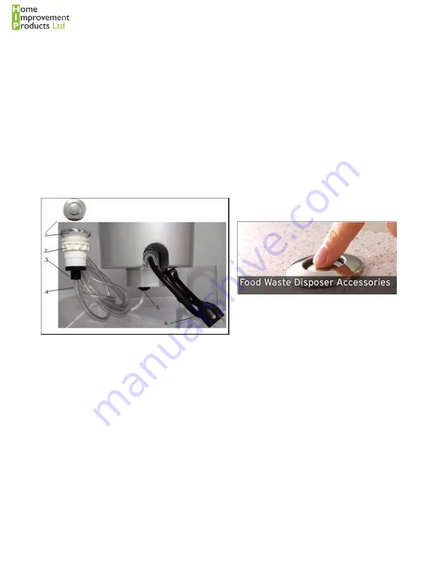
11. AIR SWITCH INSTRUCTIONS
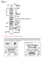
The Disposer Air Switch Assembly is supplied in three basic parts:
The Actuator which consists of:
1. Actuator Button
2. Actuator Nut
3. Actuator Outlet(Black Threaded portion)
The Air Switch Sensor is installed into disposer. Only the air tube nozzle is visible from the outside of
the disposer.
Air Tube Assembly which consists of:
1. Air Tube-Clear
2. Sensor Inlet
INSTALLATION AND OPERATING INSTRUCTIONS
The actuator button can be positioned anywhere to suit. If your sink is reversible and has a tap blanking plug
then the actuator can be fitted onto the sink itself.
Alternatively you may wish to fit the actuator to the underside of the cabinet, out of sight, or onto the kitchen
worktop.
To fit it into the kitchen worktop, you will need to do the following:-
- Drill a hole of 33mm to 35mm into the sink or countertop where the Actuator Button (#1) is to be placed.
- Insert from the top, the Actuator Outlet through the drilled hole.
- Firmly connect Air Tube (#4), one side to Actuator Outlet (#3) and one side to Sensor Inlet (#5).
Once fitted,
operating couldn’t be easier:-
Plug Disposer Power Cord(#6) into main electrical service.
To turn on disposer, press Actuator Button (#1). To turn off, press Actuator Button again.


