background image

12

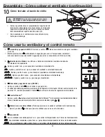
1.  

 Encendido y apagado (ON/OFF):

 Presiona y suelta el 


botón para encender o apagar el ventilador. 

y/o la luz.


Mantén presionado el


botón durante 5 segundos para usar el “temporizador inmediato”;  

esto encenderá las luces durante 30 segundos (las luces se encenderán al 50% de su brillo).

2. 

 Velocidad del ventilador: 

Los LEDs en el botón de velocidad del ventilador iluminarán  

la velocidad correspondiente.

 - Oprime y suelta 1 vez - para encender el ventilador a velocidad alta.

 - Oprime y suelta 2 veces - para encender el ventilador a velocidad media-alta.

 - Oprime y suelta 3 veces - para encender el ventilador a velocidad media-baja.

 - Oprime y suelta 4 veces - para encender el ventilador a velocidad baja.

 - Oprime y suelta 5 veces - para apagar el ventilador.

3.  

 Encendido y apagado de luces (ON/OFF) 


Oprime y suelta el botón

para encender o apagar la luz.


Si utilizas bombillas regulables y previamente configuraste el interruptor O/D del control remoto en la 

posición “D”, mantén presionado el botón 

para activar la función de regulación de intensidad.

4. 

 Comfort Breeze

TM 


Oprime y suelta el      botón

 para activar el modo Comfort Breeze

TM

. Este cambiará la velocidad del ventilador 

al azar, simulando una brisa relajante. Para cancelar esta función, oprime   o  .

5.  


Botón de reversa del ventilador

 (Tiene que presionarse cuando el ventilador esté funcionando)


  - Oprime y suelta el   botón para que el ventilador vaya en una u otra dirección.

6. 

Temporizador 


 - Con el ventilador encendido, oprime 1 vez - para activar el temporizador con 2 horas de funcionamiento.

 - Con el ventilador encendido, oprime 2 veces - para activar el temporizador con 4 horas de funcionamiento.

 - Con el ventilador encendido, oprime 3 veces - para activar el temporizador con 8 horas de funcionamiento.

Ensamblaje - Cómo colgar el ventilador (continuación)

Cómo instalar el tazón de vidrio

10


Coloca la pantalla (E) en el ensamblado del soporte del kit 
de luces (D), alineando las tres áreas planas en el reborde 
superior de la pantalla (E) con las tres muescas salientes 
del ensamblado del soporte del kit de luces (D). 


Gira la pantalla en el sentido de las manecillas del reloj 
hasta que se detenga.

D

E

ADVERTENCIA: 

Para reducir el riesgo de lesiones, espera  

que el vidrio se enfríe completamente antes de retirarla.

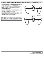
Cómo usar tu ventilador y el control remoto

G

Содержание 44-CRD

Страница 1: ...o enhance your home Visit us online to see our full line of products available for your home improvement needs Thank you for choosing Home Decorators Collection Item 1001 415 524 1001 415 523 Model 51543 51549 UL Model 44 CRD USE AND CARE GUIDE TUXFORD 44 INCH CEILING FAN To view an instructional video on how to install this product 1 Go to www homedepot com and enter either the Item or Model numb...

Страница 2: ...ts also referred to as flanges during assembly or after installation Do not insert objects in the path of the blades WARNING To reduce the risk of fire or electric shock do not use this fan with any solid state speed control device WARNING Electrical diagrams are for reference only If you are using a light kit refer to the light kit instructions manual to make the electrical connections Optional u...

Страница 3: ... defect Servicing performed by unauthorized persons shall render the warranty invalid There is no other express warranty Home Decorators Collection hereby disclaims any and all warranties including but not limited to those of merchantability and fitness for a particular purpose to the extent permitted by law The duration of any implied warranty which cannot be disclaimed is limited to the time per...

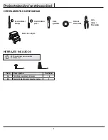
Страница 4: ...ws 16 BB Plastic wire connecting nut 3 Pre Installation continued HARDWARE INCLUDED NOTE Hardware not shown to actual size AA BB TOOLS REQUIRED Phillips screwdriver Flat blade screwdriver Adjustable wrench Electrical tape Wire cutter Stripper Step ladder ...

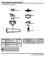
Страница 5: ...y 1 C Blade 5 D Light kit fitter assembly LED included 1 Part Description Quantity E Glass bowl 1 F Receiver 1 G Transmitter battery included 1 IMPORTANT This product and or components are governed by one or more of the following U S Patents 5 947 436 5 988 580 6 010 110 6 046 416 6 210 117 and other patents pending Pre Installation continued PACKAGE CONTENTS A B C D E F G ...

Страница 6: ...ons Disconnect the power by removing the fuses or turning off the circuit breakers Secure the outlet box directly to the building structure Use the appropriate fasteners and materials The outlet box and support structure must be securely mounted and capable of reliably supporting a minimum of 35 lbs 15 9kg Use only UL listed outlet boxes marked Acceptable for fan support of 35 lbs 15 9 Kg or less ...

Страница 7: ...g screws II in the outlet box Pass the 120 Volt supply wires through the center hole in the mounting bracket A Slide the mounting bracket A on to the mounting screws II and center the mounting bracket A in relation to the outlet box If necessary use leveling washers not included between the slide on mounting bracket A and the outlet box The flat side of the slide on mounting bracket A should face ...

Страница 8: ...The dip switches on the hand unit are located inside the battery compartment NOTE The switch marked O D controls the dimming function of the light Use a ballpoint pen or small screwdriver to switch to O to disable the dimming function The factory preset is D Setting the code on the remote control and receiver Remove the remote control G battery cover by pressing firmly on the arrow and sliding the...

Страница 9: ... wiring IMPORTANT Use the wire connecting nuts BB supplied with your fan Secure the connectors with electrical tape and ensure there are no loose strands or connections WARNING Each wire not supplied with this fan is designed to accept up to one 12 gauge house wire and two wires from the fan If you have larger than 12 gauge house wiring or more than one house wire to connect to the fan wiring cons...

Страница 10: ...nect the fan motor blue wire to the receiver blue wire using a wire connecting nut BB Secure each wire connecting nut using electrical tape Turn the wire connecting nut BB upward and push the wiring into the outlet box GG Mounting the fan motor assembly Align the locking slots of the fan motor assembly B with the two screws CC in the slide on mounting bracket A Push up to engage the slots and turn...

Страница 11: ...tter assembly D remove the one screw HH in the round hole from the switch cup JJ and loosen but do not remove the other three screws Connect the blue wire exiting the bottom of the fan motor assembly B with the black wire from the top of the light kit fitter assembly D Connect the white wire exiting the bottom of the fan motor assembly B with the white wire from the top of the light kit fitter ass...

Страница 12: ...et O D dip switch in your remote to the ON position 4 Comfort BreezeTM Press and release the button to enable Comfort BreezeTM this will change your fan speed randomly simulating a relaxing breeze To cancel this feature press or 5 Fan reverse button Must be pushed when the fan is in operation Press and release the button to forward and reverse the fan 6 Timer While the fan is on press 1 time turns...

Страница 13: ...eiling height number of fans and so on A Warm weather Forward A downward airflow creates a cooling effect This allows you to set your air conditioner on a higher setting without affecting your comfort B Cool weather Reverse An upward airflow moves warm air off of the ceiling This allows you to set your heating unit on a lower setting without affecting your comfort NOTE Do not wait for the fan to s...

Страница 14: ...hen blade levels are unequal Check this level by selecting a point on the ceiling above the tip of one of the blades Measure from a point on the center of the blade to the point on the ceiling Rotate the fan until the next blade is positioned for measurement and measure from the same point on each blade to the ceiling Repeat for each blade Any measurement deviation should be within 1 8 in Run the ...

Страница 15: ...ular installation If this equipment does cause harmful interference to radio or television reception which can be determined by turning the equipment off and on the user is encouraged to try to correct the interference by one or more of the following measures Reorient or relocate the receiving antenna Increase the separation between the equipment and receiver Connect the equipment into an outlet o...

Страница 16: ...s por Internet para ver nuestra línea completa de productos disponibles con vistas a las necesidades de mejoras de tu hogar Gracias por elegir Home Decorators Collection Artículo núm 1001 415 524 1001 415 523 Modelo núm 51543 51549 Modelo núm 44 CRD Aprobado por UL GUÍA DE USO Y MANTENIMIENTO TUXFORD VENTILADOR DE TECHO DE 1 1 M Para ver un video instructivo sobre cómo instalar este producto 1 Ir ...

Страница 17: ...e de su cumplimiento podrían anular el derecho del usuario a operar el equipo ADVERTENCIA Para reducir el riesgo de lesiones no dobles los soportes de las aspas también llamados bridas durante el ensamblaje o después de la instalación No coloques objetos en la trayectoria de las aspas ADVERTENCIA Para disminuir el riesgo de incendio o descarga eléctrica no utilices este ventilador con ningún dispo...

Страница 18: ...quier servicio prestado por personal no autorizado invalidará la garantía No hay ninguna otra garantía expresa Por este medio Home Depot Decorators Collection queda exento de todas y cada una de las garantías incluyendo pero sin limitarse a aquellas de comercialización e idoneidad para determinado propósito en el alcance permitido por la ley La duración de cualquier garantía implícita que no pueda...

Страница 19: ...lástico para conectar cables 3 Preinstalación continuación HERRAJES INCLUIDOS NOTA Los herrajes no se muestran en tamaño real AA BB HERRAMIENTAS NECESARIAS Destornillador Phillips Destornillador plano Llave ajustable Cinta de electricista Corta cables Pela cables Escalera de tijera ...

Страница 20: ...samblaje del soporte del kit de luces incluye LED 1 Pieza Descripción Cantidad E Pantalla de vidrio 1 F Receptor 1 G Transmisor incluye baterías 1 IMPORTANTE Este producto o sus componentes están protegidos por una o más de las siguientes patentes de los EE UU 5 947 436 5 988 580 6 010 110 6 046 416 6 210 117 así como por otras patentes pendientes Preinstalación continuación CONTENIDO DEL PAQUETE ...

Страница 21: ...a retirando los fusibles o apagando los cortacircuitos Asegura la caja eléctrica directamente a la estructura de la edificación Usa los sujetadores y materiales apropiados La caja eléctrica y la estructura de soporte tienen que montarse de forma segura y tener capacidad para sostener de manera confiable un mínimo de 35 lb 15 9 kg Usa sólo cajas eléctricas aprobadas por UL y marcadas como apropiada...

Страница 22: ...trica Pasa los cables de suministro de 120 voltios a través del orificio central en el soporte de montaje A Desliza el soporte de montaje A en los tornillos de montaje II y centra el soporte A en relación con la caja eléctrica Si es necesario usa arandelas niveladoras no se incluyen entre el soporte de montaje deslizante A y la caja eléctrica El lado plano del soporte de montaje deslizante A debe ...

Страница 23: ... dentro del compartimiento de la batería NOTA El interruptor marcado con ON DIM encendido regulación controla la función de regulación de intensidad de las luces Usa un bolígrafo de punta redonda o un destornillador pequeño para configurar el interruptor en la posición O y desactivar la función de regulación de intensidad El valor predeterminado de fábrica es D Configurar el código del control rem...

Страница 24: ...a las tuercas de conexión de cables BB incluidas con tu ventilador Sujeta los conectores con cinta de electricista y asegura que no haya conexiones ni cables sueltos ADVERTENCIA Cada cable no suministrado con este ventilador debe estar diseñado para aceptar hasta un cable eléctrico doméstico calibre 12 y dos cables del ventilador Si tienes un cableado doméstico que exceda del calibre 12 o más de u...

Страница 25: ... al cable azul del receptor usando una tuerca de conexión de cables BB Asegura cada tuerca de conexión de cables con cinta de electricista Gira la tuerca de conexión de cables BB hacia arriba y coloca el cableado dentro de la caja eléctrica GG Cómo montar el conjunto motor ventilador Alinea las ranuras de cierre del conjunto motor ventilador B con los dos tornillos CC del soporte deslizante de mon...

Страница 26: ...o redondo de la caja de interruptores JJ y afloja los otros tres tornillos pero sin quitarlos Conecta el cable azul que sobresale por debajo del conjunto motor ventilador B con el cable negro del ensamblado del soporte del kit de luces D Conecta el cable blanco que sobresale por debajo del conjunto motor ventilador B con el cable blanco de la parte superior del ensamblado del soporte del kit de lu...

Страница 27: ...rt BreezeTM Oprime y suelta el botón para activar el modo Comfort BreezeTM Este cambiará la velocidad del ventilador al azar simulando una brisa relajante Para cancelar esta función oprime o 5 Botón de reversa del ventilador Tiene que presionarse cuando el ventilador esté funcionando Oprime y suelta el botón para que el ventilador vaya en una u otra dirección 6 Temporizador Con el ventilador encen...

Страница 28: ...echo la cantidad de ventiladores y demás A Clima cálido Hacia delante Un flujo de aire descendente surte un efecto refrescante Esto te permite fijar tu aire acondicionado en una configuración más alta sin afectar tu comodidad B Clima frío Reversa Un flujo de aire hacia arriba desplaza el aire cálido del techo Esto te permite fijar tu unidad de calefacción en una configuración más baja sin afectar ...

Страница 29: ... problemas de oscilación del ventilador se deben a que las aspas no están al mismo nivel Verifica este nivel seleccionando un punto en el cielo raso sobre la punta de una de las aspas Mide desde un punto en el centro de cada aspa a un punto en el techo Rota el ventilador hasta que la siguiente aspa esté en posición para medir y mide desde el mismo punto en cada aspa hasta el cielo raso Repite el p...

Страница 30: ...e que no ocurrirá interferencia en una instalación particular Si este equipo causa interferencia que perjudica la recepción de radio o televisión lo cual puede determinarse encendiendo y apagando el equipo se recomienda al usuario que trate de corregir la interferencia con una o más de las siguientes medidas reorientar o reubicar la antena receptora incrementar la distancia entre los equipos y el ...

Отзывы: