


Rev. 1.50
4�
����st ��� �01�
Rev. 1.50
49
����st ��� �01�
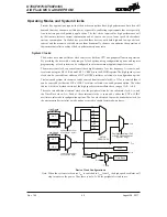
HT66F0175/HT66F0185
A/D Flash MCU with EEPROM
HT66F0175/HT66F0185
A/D Flash MCU with EEPROM
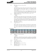
Bit 2
HTO
: High speed system oscillator ready flag
0: Not ready
1: Ready
This is the high speed system oscillator ready flag which indicates when the high
speed system oscillator is stable. This flag is cleared to “0” by hardware when the
devices are powered on and then changes to a high level after the high speed system
oscillator is stable.
Therefore this flag will always be read as “1” by the application program after device
power-on. The flag will be low when in the SLEEP or IDLE0 Mode but after a wake-
up has occurred, the flag will change to a high level after 512 clock cycles if the HXT
oscillator is used and after 15~16 clock cycles if the HIRC oscillator is used.
Bit 1
IDLEN
: IDLE mode control
0: Disable
1: Enable
This is the IDLE mode control bit and determines what happens when the HALT
instruction is executed. If this bit is high, when a HALT instruction is execured, the
device will enter the IDLE mode. In the IDLE mode the CPU will stop running but
the system clock will continye to keep the peripheral functions operational, if the
FSYSON bit is high. If the FSYSON bit is low, the CPU and the system clock will all
stop in IDLE0 mode. If the bit is low, the devices will enter the SLEEP mode when a
HALT instruction is executed.
Bit 0
HLCLK
: System clock selection
0: f
H
/2~f
H
/64 or f
SUB
1: f
H
This bit is used to select if the f
H
clock or the f
H
/2~f
H
/64 or f
SUB
clock is used as
the system clock. When the bit is high the f
H
clock will be selected and if low the
f
H
/2~f
H
/64 or f
SUB
clock will be selected. When system clock switches from the f
H
clock to the f
SUB
clock and the f
H
clock will be automatically switched off to conserve
power.
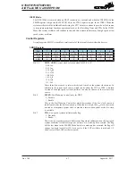
CTRL Register
Bit
7
6
5
4
3
2
1
0
Name
FSYSON
—
—
—
—
LVRF
LRF
WRF
R/W
R/W
—
—
—
—
R/W
R/W
R/W
POR
0
—
—
—
—
x
0
0
“x”: �nknown
Bit 7
FSYSON
: f
SYS
Control in IDLE Mode
0: Disable
1: Enable
This bit is used to control whether the system clock is switched on or not in the IDLE
Mode. If this bit is set to “0”, the system clock will be switched off in the IDLE Mode.
However, the system clock will be switched on in the IDLE Mode when the FSYSON
bit is set to “1”.
Bit 6~3
Unimplemented, read as “0”
Bit 2
LVRF
: LVR function reset flag
Described elsewhere.
Bit 1
LRF
: LVR control register software reset flag
Described elsewhere.
Bit 0
WRF
: WDT control register software reset flag
Described elsewhere.