background image


20 

i) Check TX’s HDMI cable is plugged well or not; 

j) Check PC,DVR or camera is powered on, and output video 

normally,here can check it with HDMI cable to connect to LED monitor or 

HD monitor; 

k) Ensure TX and RX’s location should not be less than 1.5m from the 

ground; 

l) If the image no improvement, change the TX and RX’s wireless 

communication frequency point or should shorten the wireless 

connection distance, and adjust the antenna’s direction; 


Distributed by


UL TMALINI<  SOLUTIONS 

SC:NSC:,  CONNC:CT, SC:CUMC: 

Phone: 0415 468 731,  Email: [email protected]


Suite 1A Level 2, 802 Pacific Highway, Gordon NSW 2072


www.ultralinks.com.au

Содержание HLWH009

Страница 1: ...Wireless HD Video Transmission System TX RX HLWH009 User manual ...

Страница 2: ...Preface 1 1 Cautions 2 2 About 3 3 Installation 8 4 Operation instruction 13 5 Maintenance 18 6 Truble shooting 18 ...

Страница 3: ... using this product read this user manual carefully please Follow the instruction to keep your safety and avoid products damage This user manual might be modified irregularly because of updated products And the manual is for instruction only we do not guarantee the information and the suggestions ...

Страница 4: ... product in the extreme hot cold dusty or humid environments Prevent friction with hard objects Avoid the product falling down from a high place or it may damage the hardware The product is not water proofed So do not get any liquid into the unit please Do not dismantle assemble or alter the product arbitrarily ...

Страница 5: ...ation of design and easy installation Product model and standard HLWH009 the Long Range Wireless HDMI Transmission Suite utilize today s most advanced wireless video transmission technology which can realize the broadcast class and uncompressed HDMI HD video signal transmitted with no compression and zero delay The suite includes one transmitter and one receiver both provide HDMI interface The wir...

Страница 6: ...z 480p 60 59Hz Panel 1920 1080 1768 992 1366 768 1280 768 1280 720 1280 600 1176 6 64 1024 768 800 600 720 576 720 4 80 Output Video Format HDMI 1080p 60 59 50 30 25 24Hz 1080i 60 59 50Hz 720p 60 59 50Hz 576p 50Hz 480p 60 59Hz Panel 1920 1080 1768 992 1366 768 1280 768 1280 720 1280 600 1176 66 4 1024 768 800 600 720 576 720 480 Input Audio Format I2S PCM SPDIF AC 3 DTS Dolby 5 1 7 Output Audio I2...

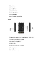
Страница 7: ...DMI 1 4 3D option Occupied Bandwidth 20 40MHz 20 40MHz Temperature Range 0 40 C operating condition 20 60 C Storage 0 40 C operating condition 20 60 C Storage Compliance FCC CE FCC CE Product introduction Transmitter 1 Connection indicator light 1 green LED 2 Digital Tube display frequency point 3 Video input indicator 1 yellow LED 4 Frequency change button ...

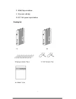
Страница 8: ...9 DC power switch 10 DC 7 36V power input interface Receiver 1 RSSI Wireless received signal strength indicator 4 Blue LEDs 2 Digital Tube display frequency point 3 Frequency change button 4 Confirm button 5 Video output indicator 1 yellow LED 6 Matching button 7 Mini USB interface ...

Страница 9: ...7 8 HDMI Output interface 9 DC power switch 10 DC 7 36V power input interface Packing list TX RX 5G high gain antennas 10pcs DC 12V 1A Adaptor 2pcs User Manual 1 piece ...

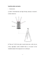
Страница 10: ...n Installation details and cautions Transmitter side a Install 5 Omni directional and high efficiency antennas to Transmitter s antenna connectors b There are 5 1 4 20 screw nuts in transmitter metal case so the user ...

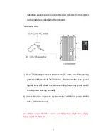
Страница 11: ...DC power interface unplug power switch make it on location then transmitter shell panel digital tube will show the corresponding frequency point which shows power working normally d Insert the video source to the transmitter s HDMI in port by HDMI cable male connector Note Please ensure that the receiver and transmitter s digital tube display frequency point is the same ...

Страница 12: ...irectional and high efficiency antennas to Receiver s antenna connectors b There are 5 1 4 20 screw nuts in receiver metal case so the user can choose appropriate location threaded holes to fix receiver on the installation bracket in the computer or fix it on the tripod ...

Страница 13: ...ake it on location then receiver shell panel digital tube will show the corresponding frequency point which shows power working normally d Use the HDMI cable connect with LED monitor or HD monitor Note Please ensure that the receiver and transmitter s digital tube display frequency point is the same ...

Страница 14: ...n Connect PC DVD and camera HDMI output to transmitter HDMI input port and connect HDMI output port of the receiver to HDMI port of the HD monitor Make sure all antennas batteries and video cable are equipped normally See below figure ...

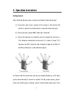
Страница 15: ...s are connected c Ensure all antennas are installed and the straight line distance is 3 5m between transmitter and receiver it is better to keep TX 5 antennas and RX 5 antennas with orthogonal angle each other for best RF performance Looks like below figure d Ensure both the transmitter and receiver installed batteries or DC input ports connected well if connect to outside 12V DC power sources ple...

Страница 16: ...rk mode fixed frequency mode and DFS mode fixed frequency mode is 0 9 DFS mode is A If need use DFS model then choose A f Before RX finished wireless connection with TX 5 RSSI indicators and Video indicators will be off during RX is connecting with TX RSSI indicators will have several lights up which shows the wireless signal has been detected to transmitter and receiver the transmitter and receiv...

Страница 17: ... LINK green and RSSI Blue light will be on if disconnection then then TX and RX s video yellow LINK green and RSSI Blue light will be off Note RSSI is the strength of signal reception i For the best wireless transmission performance it need install the transmitter and receiver more than1 5m about the ground and keep the same height and make sure no obstacles between them Moreover it is the best to...

Страница 18: ...ver will calculate received RF signal strength internally and 4 RSSI LEDs will be used to indicate wireless signal power and quality The user can observe the RSSI LED status to know if the current wireless link is reliable or not ...

Страница 19: ...ide panel of both transmitter and receiver has been installed a frequency select knob The user can touch lightly and single click CH button to choose frequency point then touch lightly and single press OK confirmation button Note Please ensure TX and RX s communication frequency point is the same similar to the intercom and support maximum 4 sets working simultaneously See below frequency knob fig...

Страница 20: ...able work conditions that battery manual mentioned 6 Trouble shooting Normal problems 1 No output on display a Check TX and RX power first and see if TX or RX is powered from external power then check normal output b Check the TX and RX s digital tube frequency point is the same and check if the antennas fixed tight c Check the straight line distance at least 3 5m between TX and RX d Check the cab...

Страница 21: ... only 1 RSSI LED lit then change both TX and RX s wireless communication frequency point or should shorten the connection distance and adjust the antenna s director as per the user manual mentioned 3 Display terminal has been on searching e Check TX is powered on and check HDMI cable is plugged well or not f Ensure TX and RX s frequency point is the same g Ensure TX and RX s location should not be...

Страница 22: ...ocation should not be less than 1 5m from the ground l If the image no improvement change the TX and RX s wireless communication frequency point or should shorten the wireless connection distance and adjust the antenna s direction Distributed by ULTMALINI SOLUTIONS SC NSC CONNC CT SC CUMC Phone 0415 468 731 Email sales ultralinks com au Suite 1A Level 2 802 Pacific Highway Gordon NSW 2072 www ultr...

Отзывы: