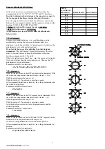


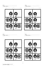

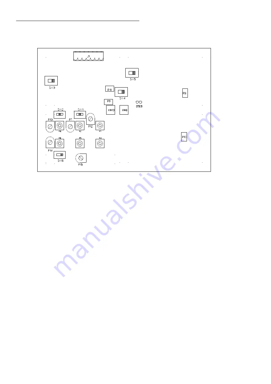
Switch and adjusttrimmers and potentiometer positions :
J1
- sensor connector (no. 5 through 11)
P1
- A adjuster
P2
- B adjuster
P3
- C adjuster
P4
- D adjuster
P5
- E adjuster
P6
- V adjuster
P7
- *manufacturer setting : adjustment maximum range B adjuster
P8
- *manufacturer setting : amplitude adjuster of the cosine circuit to make the amplitude equal to
the sine circuit (MC2/MC5)
P9
- *manufacturer setting : balance output signal of the cosine circuit
P10
- *manufacturer setting : balance output signal of the sine circuit
P11
- *manufacturer setting : amplitude adjuster of the sine circuit to make the amplitude equal to
the cosine circuit (MC4)
P12
- *manufacturer setting : balance adjuster of the A adjuster
P13
- *manufacturer setting : adjustment maximum range B adjuster
P14
- *manufacturer setting : balance adjuster of the V adjuster
P15
- 0 uT adjustmentof the V adjuster (when V adjuster is not neccessary, MC2/MC4)
SW1
- +/- switch B adjuster
SW2
- +/- switch V adjuster
SW3
- sensor selector adjuster range (MC4/MC2, MC5)
SW4
- sensor selector synchro input impendance (MC4/MC2, MC5)
SW5
- sensor selector excitation signal (MC4/MC2, MC5)
SW6
- switch V adjuster P14/P15
D5
- indication sensor selection MC2/MC5
D6
- indication sensor selection MC4
* manufacturer setting -
Do not change these settings. If settings are changed the system will
not function properly.
20
xfiles\\tek\in11\doc\handleiding_in11b_eng.lwpp
status: definite date: 30-9-2002


