background image


33

Manuel d’Utilisation

5.1.1 Démontage Pneus

AVA N T  D E   P R O C E R   A  L’ E X T R A C T I O N   D U 
PNEU  VERIFIER  SI  LES  DEUX  TALONS  SONT 
COMPLETEMENT DEJANTES.

5.1.1.1  Positionnement Outil

Procédure:

· 

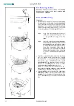
Mettre  l’outil  en  contact  avec  le  bord  de  la  jante 
et le bloquer: l’outil s’éloigne automatiquement du 
bord de la jante en sens vertical. Tourner la poignée 
de réglage jusqu’à ce que l’outil s’éloigne du bord 
de la jante à peu près de 1/25” (1 mm): celà est 
nécessaire  pour  éviter  des  dommages  à  la  jante 
(

S

, Fig. 5.1-4).

Remarque

:

  quand  l’outil  de  montage/démontage 

a été correctement positionné, les roues 
identiques  peuvent  être  montées  sans 
devoir régler l’outil de nouveau.

Remarque

:

    la  pièce  intercalaire  en  plastique  a 

l’intérieur de l’outil de montage/démontage 
doit  être  remplacée  périodiquement. 

chaque machine est fournie de diff érentes 
pièces  intercalaires  de  rechange  (dans 
la boîte des accessoires). si on le désire, 
la  pièce  intercalaire  en  plastique  peut 
être remplacée par une molette en acier 
contenue dans la boîte des accessoires. 
suivre les instructions jointes aux pièces 
de rechange.

· 

Introduire  le  levier  pour  soulever  l’enveloppe  en-
dessous du talon et au-dessus du support de l’outil. 
Soulever le talon sur la languette de montage. Pour 
rendre l’opération plus facile, appuyer, de la main 
gauche,  sur  le  fl anc  du  pneu  dans  une  position 
opposée  à  celle  de  l’outil.  Si  l’on  veut,  on  peut 
enlever le levier pour soulever l’enveloppe après 
avoir soulevé le talon sur la languette de montage 
(Fig. 5.1-5).

· 

Faire  tourner  l’autocentreur  dans  le  sens  des 
aiguilles d’une montre et en même temps, appuyer 
sur le fl anc du pneu pour maintenir le talon dans le 
creux (Fig. 5.1-6).

· 

Démonter  le  deuxième  talon  en  exécutant  les 
mêmes  opérations.  Soulever  le  pneu  de  la  main 
gauche  dans  une  position  opposée  à  l’outil  pour 
maintenir  le  talon  dans  le  creux  (Fig.  5.1-7). 
Déplacer  le  bras  déporté  latéralement  et  enlever 
le pneu.

Manual del Operador

5.1.1 Remoción neumáticos

ANTES DE EXTRAER EL NEUMÁTICO, ASEGÚRESE 
D E   Q U E   A M B O S   TA L O N E S   H AYA N   S I D O 
COMPLETAMENTE DESTALONADOS.

5.1.1.1  Colocación de la herramienta

Procedimiento:

· 

Poner  la  herramienta  en  contacto  con  el  borde 
de  la  llanta  y  bloquearla:  la  herramienta  se  aleja 
automáticamente del borde de la llanta en sentido 
vertical. Girar la manivela de regulación hasta que 
la herramienta se aleje radialmente del borde de 
la llanta unos 1/25” (1 mm): esto es necesario para 
evitar daños a la llanta (

S

, Fig. 5.1-4).

Nota: 

u n a   v e z   q u e   l a   h e r r a m i e n t a   d e 
montaje/desmontaje  ha  sido  ubicada 
correctamente, las ruedas iguales pueden 
ser desmontadas sin tener que regular de 
nuevo la herramienta.

Nota: 

el  encaje  de  plastico  dentro  de  la 
herramienta  de  montaje/desmontaje 
tiene que ser sustituido periodicamente. 
cada  máquina  lleva  algunas  piezas  de 
recambio  (en  la  caja  de  accesorios).  si 
se desea, el encaje de plastico puede ser 
sustituido por un rodillo de acero incluido 
en  la  caja  de  los  accesorios.  seguir  las 
instrucciones adjuntas a los repuestos.

· 

Introducir  la  palanca  que  levanta  la  cubierta 
debajo  del  talón  y  encima  del  soporte  de  la 
herramienta.Levan-tar  el  talón  sobre  la  lengüeta 
de montaje. Para facilitar la operación apretar con 
la  mano  izquierda  en  el  costado  del  neumático, 
en la posición diametralmente opuesta a la de la 
herramienta. Si se desea se puede quitar la palanca 
que levanta la cubierta después de haber levantado 
el talón sobre la lengüeta de montaje (Fig. 5.1-5).

· 

Hacer girar el autocentrador en dirección horaria 
y  simultaneamente  apretar  en  el  costado  del 
neumático para mantener el talón en el canal (Fig. 
5.1-6).

· 

Desmontar el segundo talón efectuando las mismas 
operaciones.  Con  la  mano  izquierda  levantar  el 
neumático en la posición diametralmente opuesta 
a la de la herramienta para mantener el talón en 
el canal (Fig. 5.1-7). Desplazar el brazo oscilante 
lateralmente y sacar el neumático.

monty 1620 - 1625

Содержание monty 1620

Страница 1: ...monty 1620 monty 1625 Operation manual Mode d emploi Manual del Operador Semiautomatic Tire Changer Démonte pneus semiAutomatique Desmontador Semi Automático de Neumáticos ...

Страница 2: ...K VII pielikuma A iedaƺai LIT už techninƳ skyriǐ atsakingas asmuo yra Ƴgaliotas sudaryti techninĊ bylą kurios sudarymo tvarka nurodyta Direktyvos 2006 42 EB VII priedo A dalyje MKD Ɉɞɝɨɜɨɪɧɢɨɬ ɧɚ ɬɟɯɧɢɱɤɢɨɬ ɨɞɞɟɥ ɟ ɨɜɥɚɫɬɟɧ ɞɚ ɝɨ ɫɨɫɬɚɜɢ ɬɟɯɧɢɱɤɢɨɬ ɩɪɢɪɚɱɧɢɤ ɞɚɞɟɧ ɜɨ ɩɪɢɥɨɝ VII ɩɢɫɦɨ A ɨɞ ɞɢɪɟɤɬɢɜɚɬɚ 2006 42 CE MON Odgovorno lice Tehniþkog ureda je ovlašteno da sastavi tehniþku fasciklu kako se vi...

Страница 3: ...not operate equipment with a damaged power cord or if the equipment has been damaged until it has been examined by a qualified authorized service technician 3 If an extension cord is used a cord with a current rating equal to or more than that of the machine should be used Cords rated for less current than the equipment may overheat Care should be taken to arrange the cord so that it will not be tr...

Страница 4: ...djustment Page 30 5 1 1Removing the tires Page 32 5 2 Mounting tubeless tyres Page 34 5 2 1 If the top tire bead is difficult to mount Page 36 5 3 Beading the tires Page 38 5 4 Demounting tube type tires Page 42 5 5 Mounting tube type tires Page 42 5 6 Inflating tube type tires Page 42 5 7 Mounting and Demounting Motorcycle tires Page 44 6 0 Maintenance Page 46 6 1 Storage Page 48 7 0 Trouble shootin...

Страница 5: ...erador page 65 ÍNDICE Señales de Seguridad página 8 1 0 Seguridad página 11 1 1 Tipografía página 15 1 2 Datos de marcación página 15 2 0 Especificaciones página 17 2 1 Condiciones página 17 3 0 Introducción página 19 3 1 Accessorios página 21 4 0 Disposición página 23 4 1 Mandos página 25 5 0 Montaje y desmontaje precauciones generales página 29 5 1 Desmontaje de neumáticos tubeless página 31 5 1 ...

Страница 6: ...k of crushing Become familiar with all controls before proceeding with operation Stand away from the bead breaker arm when in operation Apply air to breaker in bursts if necessary to control arm depth Don t allow to approach extraneous people to the service Contact with moving parts could cause injury Risk of pinching or crushing hands and fingers Keep hands and fingers clear of rim edge during demo...

Страница 7: ...l de décollage pendant le fonctionnement Appliquer l air sur l outil de décollage par à coups si nécessaire pour contrôler la profondeur du bras Empêcher les personnes étrangères au service de s approcher du démonte pneu Le contact avec des parties en mouvement peut causer un accident Risque de pincement ou d écrasement des mains et des doigts Garder les mains et les doigts à distance de sécurité ...

Страница 8: ...tilizar el equipo Mantenerse a distancia del brazo destalonador cuando está en marcha Si es necesario suministrar aire al destalonador de manera discontinua para controlar la profundidad del brazo No permitir que personas ajenas se acerquen al equipo El contacto con partes móviles puede provocar lesiones Riesgo de atrapamiento o aplastamiento de manos y dedos Mantener manos y dedos alejados del bo...

Страница 9: ...fety inflation cage designed for this purpose Lock turntable Clamp on inside of rim before attempting to inflate tire Use approved tire bead lubricant before removing or installing tire on rim ALWAYS position the Safety Restraint Arm over the wheel to hold it to the turntable while inflating if so equipped If a tire explodes on this tire changer STOP using it until the Safety Restraint Arm has been r...

Страница 10: ... A VIOLA TION OF THE SAFETY REGULATIONS THE USE OF THIS DEVICE IS ALLOWED ONLY IN LOCATIONS WITH NO EXPLOSION OR FIRE HAZARD THE INSTALLATION SHALL BE CARRIED OUT ONLY BY QUALIFIED PERSONNEL AND WITHIN THE SCOPE OF THE INSTRUCTIONS PROVIDED IN THIS MANUAL THIS DEVICE IS DESIGNED TO ACCEPT ORIGINAL SPARE PARTS AND ACCESSORIES ONLY CHECK FOR POSSIBLE DANGEROUS CONDI TIONS DURING THE OPERATION OF THE...

Страница 11: ...DOIT ÊTRE BRANCHÉ AU CÂBLE DE TERRE DE L IN STALLATION DE DISTRIBUTION Manual del Operador 1 0 Seguridad Todos los operadores deberán comprender las precauciones de seguridad y respetarlas ELOPERADOR DEBE ENCONTRARSECERCA DE LA MÁQUINA EN UNA POSICIÓN DE TRABAJO CORRECTA LADO UNIDAD DE MANDO A SÓLO EL OPERADOR PUEDE OCUPAR LA ZONA DE TRABAJO EL USO DE LA MÁQUINA ESTÁ PERMITIDO SÓLO AL PERSONAL EXP...

Страница 12: ...NGEROUS ENVIRONMENTS DON T USE PNEUMATIC OR ELECTRICAL EQUIPMENT IN DAMP OR WET LOCATIONS OR EXPOSE THEM TO RAIN KEEP THE WORK AREA WELL LIGHTED ALL ELECTRICAL CONNECTIONS MUST BE PER FORMED BY A LICENSED TECHNICIAN ALL SERVICE MUST BE PERFORMED BY AN AU THORIZED SERVICE TECHNICIAN SAFETY DEVICES This machine has several protectors made of plastic to prevent compression or crushing hazards The rot...

Страница 13: ...nflage du pneu LE CARTER DE SÉCURITÉ ET LES DISPOSITIFS DE SÉCURITÉ DOIVENT ÊTREACTIFS ET DOIVENT FONCTIONNER CORRECTEMENT Manual del Operador ANTES DE REALIZAR CUALQUIER OPERACIÓN DE MANTENIMIENTO O REPARACIÓN HAY QUE DESCONECTAR LA MÁQUINA DE LA RED DE SUMINISTRO ELÉCTRICO Y DE LA LINEA DE AIRE COMPRIMIDO NO USAR NUNCA CORBATAS CADENAS U OTROS ACCESORIOS SEMEJANTES AL RE ALIZAR OPERACIONES DE USO...

Страница 14: ...ist indicates that action must be taken by the operator before being able to go to the next step in the sequence A dotted line around the number of the figure indicates that this is a duplicate from a previous section 1 2 Label of the constructor A marking label attached to the machine shows the following data Fig 1 2 1 a Name and address of the manufacturer b EC compliance marking c Year of manufa...

Страница 15: ...Numéro de série f Poids g Caractéristiques électriques volt ph Hz kW et A h Pression air comprimé i Emission acoustique Manual del Operador 1 1 Tipografía Este manual contiene estilos de texto para llamar su atención especial Nota Sugerencia o explicación PRECAUCIÓN SIGNIFICA QUE LA ACCIÓN SIGUIENTE PUEDE CAUSAR DAÑO A LA UNIDAD U OBJETOS ACOPLADOS AVISO SIGNIFICA QUE LA ACCIÓN SIGUIENTE PUEDE CAU...

Страница 16: ...side locking 10 20 1620 Rim diam inside locking 12 24 1620 Motorcycle adapters 12 23 1620 ATV adapters 8 18 1620 Automobile extensions 16 26 1625 Rim diam outside locking 10 24 1625 Rim diam inside locking 12 24 1625 Motorcycle adapters 12 26 1625 ATV adapters 8 23 1625 Automobile extensions 17 28 Acoustic pressure 70dBA Acoustic pressure bead seater 120dBA Dimensions in inch millimeters Fig 2 1 L...

Страница 17: ...amais dépasser Plage de températures 0 50 C Plage d humidité 10 90 sans condensation option Manual del Operador 2 0 Especificaciones Desmontadora de neumáticos electro neumática para automóviles furgones y motos con neumáticos montados en llantas acanaladas Peso 512 lbs 233 Kg Presión aire psi 110 170 8 12 bar Fuerza destalonador lbs 3300 15 kN Especificaciones Eléctricas 120 VAC 1 ph 60 Hz Motor mo...

Страница 18: ...lly demounting mounting and beading car and motorcycle tIres mounted on one piece rims with the following specifications Maximun tIre diam 50 mm 1270 Maximum tIre width 15 380 mm This device must be used in the application for which it is specifically designed Any other use shall be considered as improper and thus not unreasonable The manufacturer shall not be considered liable for possible damage c...

Страница 19: ...ent au Ch 9 Annexes DECLARATION CE Le document original figurant dans le Liste des pièces détachées Manual del Operador 3 0 Introducción Felicitaciones por haber comprado el desmontador de neumáticos HOFMANN monty Construido para el empleo de profesionales que trabajan intensamente este desmontador de ruedas es de uso sencillo seguro y fiable Con un mínimo de mantenimiento y de cuidado este desmonta...

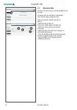
Страница 20: ... After accessing the website proceed as follows Select Accessory Plan 1 Access the specific page for Accessories Select the reference Brand in the field Brands 2 Select the Type of product Tyre changers in the field Product lines 3 Open the field Model 4 and select the specific machine model among the ones in the list Enter SEARCH 5 to display the list of available accessories monty 1620 1625 ...

Страница 21: ...de machine désiré dans la liste Taper SEARCH 5 pour afficher la liste des accessoires disponibles Manual del Operador 3 1 Accesorios Normalmente la máquina dispone de una serie de accesorios La lista completa está disponible en el sitio web http service snapon equipment net Después de acceder a la página web realizar las operaciones siguientes Seleccionar Accessory Plan 1 Se accede a la página relat...

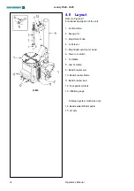
Страница 22: ...de 2 Swing arm 3 Adjustment knob 4 Lock lever 5 Mount demount tool or head 6 Tower or column 7 Turntable 8 Jaw or clamp 9 Bead breaker arm 10 Bead breaker blade 11 Bead breaker pad 12 Foot pedal controls 13 Inflation gauge Tubeless system machines only 14 Bead seater inflator pedal 15 Air Jets monty 1620 1625 ...

Страница 23: ...r 13 Manomètre de gonflage Dans le modèle tubeless seulement 14 Pédale de gonflage 15 Gicleurs Manual del Operador 4 0 Disposición Consultar Figura 4 1 Descripción funcional de la unidad 1 Barra vertical 2 Brazo oscilante 3 Manivela de regulación 4 Palanca de bloqueo 5 Herramienta 6 Columna 7 Autocentrante 8 Garra 9 Brazo destalonador 10 Paleta destalonadora 11 Soportes destalonadores 12 Pedales 13 ...

Страница 24: ... bead breaker blade will retract C Press down and hold WITH RIGHT FOOT the first pedal from the right the turntable turns clockwise 7 or 7 14 rpm Lift the pedal and the turntable turns counter clockwise 7 rpm DANGER OF LEG TRAPPING D The lock handle enable the mount demount tool to be locked in the working position Lower the lock handle to unlock Fig 4 1 2 the vertical slide lift the handle to lock...

Страница 25: ... LUNETTES DE PROTECTION POUR ÉVITER LA CONTAMINATION PAR LA POUSSIÈRE ET LES IMPURITÉS SOULEVÉES PAR LES JETS D AIR Manual del Operador 4 1 Mandos Antes de trabajar con la máquina hay que estar bien seguro de que se ha comprendido bien la posición y las funciones de los mandos Fig 4 1 1 A Apretar y soltar CON ELPIE IZQUIERDO el primer pedal de la izquierda las garras del autocentrante se mueven ha...

Страница 26: ...D CHIPS BLOWN BY THE AIR JETS DANGER OF TIRE EXPLOSION Presetting of clamping jaws if any N B Turntable capacity can be changed before pedal control The turntable jaws can be positioned in two different ways Fig 4 1 5 Push the lever C on the left side of each jaw and shift at the same each one 0 4 VERY IMPORTANT LOOK FOR PROPER INSER TION OF THE PIN CAUTION MAKE SURE ALL FOUR CLAMPING JAWS ARE MOUN...

Страница 27: ... 1 Dans la position 2 des mors Fig 4 1 5 Pos 2 il faut ajouter 4 pouces Manual del Operador Sólo para el modelo Tubeless F1 Apretar hasta la mitad el pedal de hinchado 1 Fig 4 1 3 del extremo del tubo de hinchado sale aire 2 Fig 4 1 3 F2 Apretar el pedal del inflador 1 Fig 4 1 3 hasta el fondo para accionar los chorros de aire del extremo de las boquillas 3 Fig 4 1 3 Nota Contemporáneamente seguirá...

Страница 28: ...E WEIGHTS INSIDE THE RIM B THE TIRE MUST BE CLEAN AND DRY WITH NO DAMAGE TO THE BEAD AND THE CASING C REPLACE THE RUBBER VALVE STEM WITH ANEW ONE OR REPLACE THE O RING IF THE VALVE STEM IS MADE OF METAL D IFTHETIRE REQUIRESATUBE MAKE SURE THE TUBE IS DRY AND IN GOOD CONDITION E LUBRICATIONISNECESSARYFORCORRECT MOUNTING OF THE TIRE AND PROPER CENTERING USE ONLY AN APPROVED LUBRICANT FOR TIRES F MAK...

Страница 29: ... VÉRIFIER SI LE PNEU EST DE LA JUSTE DIMENSION POUR LA JANTE Manual del Operador 5 0 Montaje y desmontaje precauciones generales ATENCIÓN ANTES DE MONTAR EL NEUMÁTICO EN UNA LLANTA RESPETAR LAS SIGUIENTES INDICACIONES A LA LLANTA DEBE ESTAR LIMPIAY EN BUEN ESTADO SI FUERA NECESARIO LIMPIARLA DESPUÉS DE HABER QUITADO TODOS LOS CONTRAPESOS COMPRENDIDOSLOSPESOS ADHESIVOS QUE SE HUBIERAN APLICADO DENT...

Страница 30: ...ls 14 or smaller from the outside set the clamps at diameter nearly equal to the rim diameter before placing the wheel on the clamps This will avoid the risk of pinching the tire WARNING TO MINIMIZE THE RISK OF SCRATCHING ALLOY RIMS THESE SHOULD BE CLAMPED FROM THE OUTSIDE Liberally lubricate bead and rim Place the wheel WITH DROP CENTER UPWARDS Fig 5 1 2 on the turntable and clamp in position 5 1...

Страница 31: ...ngulaire souhaitée 5Serrer la vis inférieur 1 au couple de 35 Nm Manual del Operador 5 1 Desmontaje de neumáticos tubeless Quitar todos los contrapesos de los bordes de la llanta Quitarla válvula ydesinflarlarueda Fig 5 1 0 Destalonar el lado exterior comenzando desde una posición diametralmente opuesta a la válvula Lubricar el talón y la llanta con un lubricante específico Destalonar el talón inte...

Страница 32: ...eral plastic inserts inside standard equipment box if desired the plastic insert may be replaced by a steel roller also included in the standard equipment box follow the instructions included with the replacement parts Insert the bead lifting tool under the bead and over the support of the mount demount tool Lift the bead onto the mounting finger To facilitate this operation press with left hand on...

Страница 33: ... creux Fig 5 1 7 Déplacer le bras déporté latéralement et enlever le pneu Manual del Operador 5 1 1 Remoción neumáticos ANTES DE EXTRAER ELNEUMÁTICO ASEGÚRESE DE QUE AMBOS TALONES HAYAN SIDO COMPLETAMENTE DESTALONADOS 5 1 1 1 Colocación de la herramienta Procedimiento Poner la herramienta en contacto con el borde de la llanta y bloquearla la herramienta se aleja automáticamente del borde de la lla...

Страница 34: ...o have the valve in 5 o clock position Place the tire to be mounted on the rim Swing the mounting arm forward so that the mount demount tool is in the working position Engage the lower bead OVER the mounting wing and UNDER the mounting finger of the mounting tool Turn the wheel clockwise and push the tire down into the drop center opposite to the mount demount head Fig 5 2 3 Mount the upper bead fo...

Страница 35: ...tiliser l étau de montage MX en option EAA0247G70A Fig 5 2 4 Manual del Operador 5 2 Montaje de neumáticos tubeless en llantas acanaladas Lubricar toda la superficie de la llanta Fig 5 2 1 Lubricar los dos talones del neumático dentro y fuera con un lubricante para neumáticos Fig 5 2 2 SI FUERA NECESARIO RESPETAR LA DIRECCION DE ROTACION DEL NEUMATICO ALGUNOSNEUMATICOSTIENENUNPUNTODE COLOR QUE TIEN...

Страница 36: ...024180 optional B Step on the foot pedal to rotate the turntable clockwise until the tire lever is tight against the bead head Fig 5 2 1 1 C Using your right hand push and hold the tire bead opposite the bead head into the rim drop centre D Position the bead clamp MX EAA0247G70A optional to hold the tire bead into the rim drop centre Fig 5 2 4 E As the turntable is turning use the tire tool in you...

Страница 37: ...er ou l outil de montage avant de relâcher la pédale de rotation Manual del Operador 5 2 1 Si el talón superior del neumático es difícil de montar Opción 1 Utilice el Bead Assist accesorio opcional MH310 PRO Siga las instrucciones por separado siempre Opción 2 Siga estas instrucciones con la abrazadera MX opcional Fig 5 2 4 EAA0247G70A A Una vez instalado el talón inferior introducir la palanca qu...

Страница 38: ...RESSURE BEFORE BEADING CHECK THE CONDITION OF TIRE AND RIM CHECK FOR CORRECT SEALING BETWEEN THE VALVE AND THE FITTING AT THE END OF THE AIR HOSE AN AIR LEAK CAN GIVE INCORRECT PRESSURE READINGS AND CREATE SAFETY HAZARDS CHECK THAT THE READING ON THE PRESSURE GAUGE IS ZERO WHEN IT IS NOT IN USE THE COMPLETE SEATING THE BEAD ON THE RIM ISAVERY DANGEROUS STAGE OF THE TIRE MOUNTING PROCEDURE TO COMPL...

Страница 39: ...LESLOGEMENTSDELAJANTEDANSUN TELCASN ESTPASGARANTIEETPEUTREPRESENTERUN DANGER POUR LES OCCUPANTS DU VEHICULE Manual del Operador 5 3 Entalonado de los neumáticos Por Entalonado se entiende una adherencia inicial de los talones del neumático a la llanta tal que permita continuar con la operación de inflado y sucesivo asentamiento de los mismos en sus alojamientos en la llanta Precauciones de Segurida...

Страница 40: ... pedal control or with the inflator gauge Figura 5 3 1 Beading with the GP device The machine can be provided with a GP device necessary for bead seating of tubeless tires Figure 5 3 2 If possible lock the wheel from inside Outside locking reduces efficiency of the bead seater Connect the compressed air hose to the valve 2 Lift the tire with both hands so that upper bead is sealed to the rim edge Fig...

Страница 41: ...TOIRE LES GICLEURS D AIR POUVANT PROJETER IMPURETES ET POUSSIERES Manual del Operador Entalonado de Neumáticos Tubeless Realizar el entalonado con la rueda bloqueada sobre el desmontador de ruedas Asegúrese de que ambos talones y toda la llanta estén esmeradamente lubricados Enrosque el inserto válvula Conecte el tubo del aire comprimido a la válvula 2 Figura 5 3 2 Accione el mando del aire compri...

Страница 42: ...E BEAD BREAKING OPERATION THE VALVE SHOULD BE OPPOSITE TO THE BLADE OF THE BEAD BREAKER To demount the first bead place the valve at 3 o clock position DO NOT CATCH THE TUBE WITH THE BEAD LIFTING TOOL WHEN LIFTING THE BEAD ON THE MOUNTING FINGER After demounting the first bead remove the tube before demounting the second bead as described in section 5 1 5 5 Mounting tube type tires Proceed as descri...

Страница 43: ...e premier Manual del Operador 5 6 Hinchado de neumáticos con camara de aire Desbloquear la llanta y comenzar a hinchar el neumático empujando la válvula hacia dentro para evitar que se formen burbujas de aire entre la cámara de aire y la cubierta Fig 5 6 1 Controlarqueelneumáticoestébiencentradosobrelallanta DETENGAELMANDOINMEDIATAMENTEDESPUÉS DE HABER LOGRADO UNA BUENAADHERENCIA DE LOS TALONES A ...

Страница 44: ...ional motorcycle adaptors EAA0329G53A 4 piece and EAA0247G14AMotorcycle bead breaker blade The bead breaking mounting and demounting technique is the same as per car tires MOTORCYCLERIMSMUSTALWAYSBECLAMPED FROM THE OUTSIDE AIR PRESSURE TO THE TIRE CHANGER MUST NOT EXCED 140 PSI 10 BAR WHEN CLAMPING MOTORCYCLE RIMS monty 1620 1625 ...

Страница 45: ...ACHINE NE DOIT PAS DÉPASSER LES 140 PSI 10 BAR QUAND ON BLOQUE LES JANTES MOTO Manual del Operador 5 7 Montaje y Desmontaje de neumáticos de Motos Para trabajar con neumáticos de motos es necesario montar los adaptadores especiales EAA0329G53A 4 piezas con conexión rápida en las garras del autocentrante EAA0247G14A Paleta destalonador moto La técnica de destalonado de montaje y desmontaje es la mi...

Страница 46: ...able with a nonflammable liquid detergent dry and lubricate the sliding surface of the clamps with oil C Clean the teeth of the clamps A with a wire brush check the plastic rim protectors B and replace if worn Fig 6 2 D Periodically wash all plastic parts with cold water and soap or mild chemical detergent E Periodically lubricate rods of air cylinders with oil F Peridically replaced the plastic in...

Страница 47: ...ntage démontage G Contrôler les supports du détalonneur s ils sont détériorés les remplacer Manual del Operador 6 0 Mantenimiento ANTES DE COMENZAR CUALQUIER OPERACION DE MANTENIMIENTO FIJARSE QUE LAMÁQUINA ESTE DESCONECTADA DE LA LINEA ELECTRICA Y DE LA LINEA DE AIRE COMPRIMIDO A Limpiar periódicamente la barra hexagonal vertical con detergente líquido no inflamable Lubricar con aceite Fig 6 1 B L...

Страница 48: ...15 BP ENERGOL WT3 TOTAL LOBELIA SB 15 ESSO MARCOL 82 J Periodically check the lubricator efficiency One oil drop G Fig 6 3 every 4 5 operations of the bead breaker indicates that the correct amount of oil is being dispersed in the system If necessary adjust the oil flow with screw R Fig 6 3 K If the machine is also equipped with a beading unit for tubeless tires drain condensation from the tank dail...

Страница 49: ...n check first the condition of all previously protected parts and check for correct functioning of all devices before using the machine again Manual del Operador H Vaciar cada dia el agua del filtro F tirando hacia abajo el vaciado rápido S Fig 6 3 I Controlar regularmente el nivel del aceite Cuando se añade aceite al lubricador primero desconectar la línea de aire y añadir la cantidad de aceite nec...

Страница 50: ...lectric power Check that the electric plug is correctly fitted to the socket and that the electric power is on 2 Switch or motor short circuited Check that the electrical requirements of the machine are the same as the supply Call the authorized service center for assistance The switch pedal does not return to neutral position 1 Switch spring is broken Lift the pedal to neutral position Disconnect ...

Страница 51: ...a vanne Vérifier la pression de l air dans le réseau d alimentation 2 Joints cylindre détériorés Appeler un centre de service après vente autorisé Manual del Operador 7 0 Resolución de problemas Si ocurre algún problema en el desmontador proceda en el siguiente orden para resolverlo 1 Recuerde los últimos pasos dados Ha trabajado de acuerdo con el manual Funcionaba la unidad tal y como se describe...

Страница 52: ...Low air pressure Check air pressure 4 Jaw teeth worn out Check jaws condition Call the authorized service center for assistance Machine damages rims 1 Plastic insert in mount de mount tool worn out Replace the plastic insert in the mount demount tool 2 Plastic protector in jaws worn out Replace plastic protector in jaws monty 1620 1625 ...

Страница 53: ...ion en plastique de la tête 2 Protection mors détériorée Substituer la protection des mors Manual del Operador No aprieta las llantas 1 Garras sucias Limpiar las garras 2 Autocentrador sucio Limpiar el autocentrante 3 Poca presión Controlar la presión del aire en la línea de alimentación 4 Garras desgastadas Controlar las condiciones de las garras Llamar al centro de asistencia autorizado para la ...

Страница 54: ...ower supply cable close to where it comes out of the machine 2 DO NOT dispose of the equipment as urban waste and recycle it by taking the materials to suitable recycling centres 3 Contact the reseller for the closest authorised recycling centres for the disposal or for the collection of old equipment when purchasing new equipment 4 Sticktothestandardsforcorrectwastemanagement to prevent potential...

Страница 55: ...oter que la configuration exacte peut différer dans votre pays Se reporter au bon de commande pour de plus amples renseignements Manual del Operador 8 0 Eliminación de la unidad Para el desguace del aparato al final de su vida útil póngase en contacto con el revendedor para que le haga una oferta o para conocer las normas aplicables en materia de eliminación de la unidad Este símbolo indica la obliga...

Страница 56: ...56 B L A N K P A G E monty 1620 1625 ...

Страница 57: ...57 Annexe Instructions pour l Installation Appendix Installation Instructions Anexo Instrucciones Instalación monty 1620 1625 ...

Страница 58: ...rized persons and of objects which may create possible hazards The machine shall be installed on a horizontal floor preferably even Do not install the machine on a sinking or irregular floor If the machine is installed on a raised floor the floor must have a capacity of at least 110lbsxsqft 5000 N m o 500 kg m The machine must be secured to the floor through the holes provided in the cabinet Expansion ...

Страница 59: ... une clé dynamométrique étalonnée à 51 ftxlb 70 Nm Manual del Operador i Requisitos de Instalación LA INSTALACIÓN TIENE QUE SER EFECTUADA POR PERSONAL CALIFICADO EN EL TOTAL RESPETO DE LAS INSTRUCCIONES DADAS EN ESTE MANUAL Instalar la máquina en un sitio cubierto y seco La instalación de la máquina necesita un espacio útil de 106 x106 270x270cm Fig i 1 Fijarse que desde su posición de mando el tr...

Страница 60: ...removing the carton check for any visible damage to the machine and its components In case of doubt call qualified personnel for assistance The packing materials plastic bags polystyrene nails screws wood etc must be properly disposed of Place the above mentioned materials into a trash container and dispose per local regulations ALWAYS WEAR GLOVES WHEN UNCRATING THE MACHINE TO PREVENT SCRATCHES OR ...

Страница 61: ...ages métalliques pour l élingage Utiliser des courroies de 3000 mm 10 de longueur et de Kg 500 1100 lbs de portée Manual del Operador ii Transporte Desembalaje Tran sporte Transporte La máquina se entrega embalada en una caja de cartón de resistencia adecuada Esta caja a su vez está colocada en un pallet de transporte Para el transporte de la máquina embalada hay que emplear un medio adecuado de e...

Страница 62: ... the earth wire to a live terminal Check that the power supply has an automatic circuit breaker with a differential circuit rated at 30 mA The electric motor operates in a wide voltage range plus or minus 10 and frequency range 60 Hz and has a class of insulation suitable for hot and moist climates NOTE AIR MOTOR POWERED MACHINE DOESN T NEED ELECTRICAL INSTALLATION Pneumatic installation THE AIR IN...

Страница 63: ...faut installer un régulateur de pression avant la prise d air de la machine Manual del Operador iii Procedimiento de Instalación Conexión eléctrica LAINSTALACIÓNTIENEQUESEREFECTUADAPOR PERSONALCALIFICADOENELTOTALRESPETODE LAS INSTRUCCIONES DADAS EN ESTE MANUAL Controlar que las características eléctricas indicadas en la placa de datos del fabricante correspondan con las de la instalación La máquin...

Страница 64: ...FORMANCE BEFORECONNECTINGTHEMACHINETOTHEAIR SUPPLYBESURETHATNOTHINGISLEFTONTHE TURNTABLE AREA TOOLS ETC After ensuring all the above proceed as follows Connect the machine to the air supply max pressure of 12 bar 170 psi with a rubber hose rated for the pressure with an inside diameter of 6 mm 1 4 Fig iii 1 To install any accessory on request follow the instructions enclosed with it In case of ins...

Страница 65: ...a machine est installée par un technicien de service Expliquer à l opérateur la façon de mettre en marche et d arrêter l unité Manual del Operador comprimido para reducir la cantidad de agua en la línea PARA LA VERSIÓN CON MOTOR ELÉCTRICO Conecte la máquina a la línea de aire comprimido con una manguera de goma capaz de soportar la presión de 6 mm de diámetro interior NPT se proporciona a la entra...

Страница 66: ...66 B L A N K P A G E monty 1620 1625 ...

Страница 67: ...67 B L A N K P A G E monty 1620 1625 ...

Страница 68: ...all not be liable for errors contained herein or for incidental consequential damages in connection with furnishings performance or use of this material This document contains proprietary information which is protected by copyright and patents All rights are reserved No part of this document may be photocopied reproduced or translated without prior written consent of Snapon Equipment 309 Exchange ...

Отзывы: