


17
GB
03 Test
run
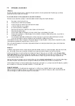
After doing the steps indicated in point 2, you can go to the test run. You should clean the bathtub, then
fi
ll the bath with
water at 40+/- 5 ºC and start the system for 10 minutes, checking the max/min. number of rotations. Then, the whirpool
system should be turned on, and after next 10 minutes, all the pipes, wires and connection tightness should be checked.
During restarting, disinfection should be started according to instructions in 14 paragraph.
After installation and leak test it is necessary not later than within 24 hours after
fi
lling of water and emptying the bathtub
to clean it and protect it from damage during the construction phase. If the above condition is not followed, the warranty
is not valid.
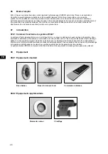
04 Bathtub
apron
After the test run, install glass apron according to the instructions or build in the bathtub taking into consideration the
following points:
1.
All systems of conduits and components of the system initially installed in the bathtub and the ones installed
at the factory must rest freely behind the walling.
2.
The displayed system components,
fi
rst of all the fan side of the pump, should be protected against dirt by
covering them.
3.
Mount the apron in such a way that the system components are protected against touching and water splashing.
The bathtub’s operation without the apron is not allowed, except for the test run.
4.
3-4 mm width gap for silicon seal should be left between the edge of the bathtub and the apron (according to the
usage instructions by the producer)
5.
In case of all models, place easily accessible and easily opening inspection windows min. 400 to 450
mm wide and 350 mm high, according to annexed drawings with dimensions.
Moreover, allow for an inspection window near the outlet.
The inspection window can be opened only with the use of proper tools. The given dimensions should be
absolutely maintained, because in case of a need for maintenance only then it is possible to easily disassemble
the system components. An ideal solution is placing the „air and inspection grate” produced by Hoesch,
dimensions 420 x 325 mm (article No. 6683.---).
6.
On account of the rotating jets and the blower a free inlet of air should be provided (approx. Vo = 60,0 m³/h
with the max. number of revolutions of the blower), because when the casing is hermetically tight there
is no inlet of air to the rotating jets and to the blower. A hole with the dimensions 100 x 100 mm in the casing
is suf
fi
cient. The use of the „air and inspection grate” will provide suf
fi
cient in
fl
ow of air.
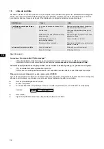
05 Diagram
1
2
4
5
6
7
7
8
8
1
3
9
350
min.400
350
min.400
1 The steering connection to the mains 230V~,
50/60 Hz, 10 A connection box self- provided
2 Pilot
3 Pump
4 Controller
5 Blower
6 Controller
7 Underwater LED lighting
8 Inspection opening
9 Control panel
Содержание ERGO+ Series
Страница 65: ...RU 65 02 02 1 L 1 L 2 L 3 N PE 9 RCD 30 mA 4 mm 60 cm 60 cm 60 cm 225 cm r 6 0 c m...
Страница 68: ...RU 68 06 HOESCH 07 07 01 ERGO 1 ERGO 08 08 01 08 02...
Страница 70: ...RU 70 10 11 Hoesch 12 25 25 1 4 13 20 2 30 90 14 2 3 o 69 23 133607 100 100 133607 10 3 30 1 27 2 30...
Страница 71: ...RU 71 15 1 32 C 37 C HOESCH HOESCH 699100...
Страница 72: ...RU 72 16 230 50 FI 1 HOESCH HOESCH Fabr Nr 0H7 00008...
Страница 78: ...CN 78 06 HOESCH 07 07 01 ERGO 1 bar ERGO 08 08 01 08 02...
Страница 79: ...CN 79 1 2 4 5 3 6 7 Whirlpower Air 8 Whirlpower 9 LED 10 3 11 1 3 4 5 6 7 8 9 11 10 2 09 ERGO 1 2 1 2 10...
Страница 81: ...CN 81 HOESCH HOESCH 699100 16 230 V 50 Hz FI 1 HOESCH HOESCH Fabr Nr 0H7 00008...
Страница 82: ...82...
Страница 83: ...83...


