

Table 3
* When a low battery condition is indicated, both, main and secondary, batteries must be
changed altogether.
TECHNICAL SPECIFICATIONS
Communication range with the
translator or expander
100 m
Open space
Operating frequency
916 MHz
Modulation type
FSK
Operating frequency channels
6
Radiated power
5 dBm (3 mW)
Typical
Transmission message period
60 sec
Default
Main battery
*
Type CR123A (3 Vdc)
5 years typical
Secondary battery
*
Type CR2032
А
(3 Vdc)
2 months typical
Dimensions
110 mm x 65 mm
Including adaptor wall
base
Weight
130 g
Including adaptor wall
base
IP rating
21C
Max tolerated humidity
(no condensing)
95% RH
Operating temperature range
From –10 °C to +55 °C
Required programming software
“Wirelex-Fire” revision
5.1.3 and successive
Minimum required Vega interface
firmware version for the translator
FW v2.01
For magnet test
5) After all detectors have been inspected and serviced, reinstall them in their mounting bases, re-apply power to the system and
check correct operation as described under the TESTING paragraph.
FAULT SELF-TEST
The wireless heat detector periodically performs a self-test and, if a fault condition is detected, a fault message is sent to the control
panel via translator / expander.
The fault condition is locally signaled by the visual LED indicator located at the center of the detector (see Table 1).
A fault condition is determined by:
a) Fault on the thermal electronic circuit, etc.
b) Low batteries level.
IMPORTANT! - THERMAL ALARM THRESHOLD SETTING
Thermal alarm threshold setting can be programmed
ONLY THROUGH THE PC’S WIRELEX CONFIGURATION PROGRAM AND
ONLY DURING WIRELESS SYSTEM CONFIGURATION; IT CANNOT BE CHANGED AFTER!
Thresholds level characteristics are illustrated in table 4 (default is A1R).
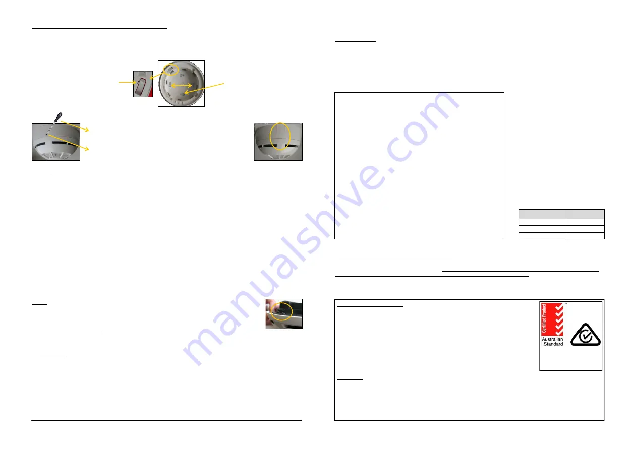
60 mm
Picture 6 - Detector block and holes for the screws
Detector block. Remove the small
plastic lug on the plastic blocking grip,
to allow the block of the detector
Holes to screw the base onto the wall
Picture 7 - Detector block removal
Tool to remove the
blocked detector
Hole to unblock the detector
WIRELESS DETECTOR ANTI-TAMPER BLOCK AND REMOVAL
The base for the wireless heat detector has a special anti-tamper device block. To lock the sensing device onto the base, cut off the
small plastic lug
on the plastic blocking grip on the detector base (Picture 6).
To remove the blocked detector from the base, insert a tool, like a small screwdriver, into the hole and remove the detector
(Picture 7).
TESTING
Detectors should be tested after installation and during periodic maintenance visits.
Detectors can be tested as follows:
Magnet test
The wireless optical smoke detector has been designed to permit a magnetic functional test. To perform the magnetic test put and
hold the magnet near the surface of the indicated area (Picture 8).
Heat test
Use a hair dryer of 1000-1500 W or an heat tool from an approved manufacturer. Direct the heat towards the sensor from its side.
Hold the heat source at about 15 cm away from the sensor in order to prevent damage to its cover during testing.
When this test is performed:
1) The detector must enter into alarm condition, activating the central LED indicator (blink red as per Table 1).
2) Transmit the fire alarm message to the control panel via translator / expander.
3) An alarm condition on the control panel should be triggered.
If the detector does not respond to the test correctly it may be necessary to clean it: in this case follow the instructions indicated in the
“MAINTENANCE” paragraph.
If testing fails again after maintenance then replace the detector with a new one and return the faulty one for servicing.
After every test, the detector must be reset by the specific command on the control panel (see the RESET paragraph).
RESET
To reset the detector from alarm or fault condition it is necessary to send the reset
command from the control panel.
TAMPER DETECTION FEATURE
The wireless heat detector is provided with a tamper switch and, in case of removal of the detector from its base, it sends a tamper
detection message to the control panel (Picture 9).
MAINTENANCE
1) Before starting any maintenance work, isolate and disable the system, in order to avoid accidental and unwanted alarm
conditions.
2) Remove the detector from its mounting base to allow inspection and servicing at ground level and in good light.
Inspect the thermistor area: use a small, soft bristle brush to dislodge any obvious contaminants such as insects, spider webs,
hairs, etc.
3) Use a small vacuum tube or dry, clean, compressed air to suck up or blow any remaining small particles away from the thermistor.
4) Wipe the exterior housing of the detector with a clean, damp, lint-free cloth to remove any surface film that can later
attract airborne contaminants.
HOCHIKI EUROPE (UK) LTD
, Grosvenor Road - Gillingham Business Park - Gillingham -
Kent ME8 0SA - U.K.
www.hochikieurope.com
L20-SG350-6100 (v1.1)
Picture 9 - Tamper switch
Threshold levels
Value
Fixed
58 °C
A1R
(rate of rise)
58 °C
High temperature
78 °C
Table 4 - Thermal alarm thresholds
Picture 8 - Magnetic test area:
correct position for magnet test
WARNINGS AND LIMITATIONS
Our devices use high quality electronic components and plastic materials that are highly resistant to
environmental deterioration. However, after 10 years of continuous operation, it is advisable to
replace the devices in order to minimize the risk of reduced performance caused by external fac-
tors. Ensure that this device is only used with compatible control panels. Detection systems must be
checked, serviced and maintained on a regular basis to confirm correct operation. Smoke sensors
may respond differently to various kinds of smoke particles, thus application advice should be
sought for special risks. Sensors cannot respond correctly if barriers exist between them and the
fire location and may be affected by special environmental conditions. Refer to and follow national
codes of practice and other internationally recognized fire engineering standards. Appropriate risk
assessment should be carried out initially to determine correct design criteria and updated periodi-
cally.
WARRANTY
All devices are supplied with the benefit of a limited 3 year warranty relating to faulty materials or manufacturing defects, effective
from the production date indicated on each product. This warranty is invalidated by mechanical or electrical damage caused in the
field by incorrect handling or usage. Product must be returned via your authorized supplier for repair or replacement together with
full information on any problem identified. Full details on our warranty and product‟s returns policy can be obtained upon request.
The warranty does not cover the provided batteries.
ABN 67 153 750 648
SAI Global
Lic SMK40120
Lic SMK40119
AS7240.5-2004
AS4428.9-2006
Class A1R


