


- 3 -
4.
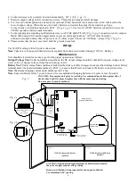
Connect devices to be powered to terminals marked [+ DC –]
(Fig. 2, pg. 3)
.
5.
Measure output voltage before connecting devices. This helps avoiding potential damage.
6.
For Access Control applications, batteries are optional. When batteries are not used a loss of AC will result in the
loss of output voltage. When the use of stand-by batteries is desired, they must be lead acid or gel type.
Connect battery to terminals marked [+ BAT –]
(Fig. 2, pg. 3)
. Use two (2) 12VDC batteries connected in series for
24VDC operation (battery leads included).
7.
Connect appropriate signaling notification devices to AC FAIL & BAT FAIL
(Fig. 2a, pg. 3)
supervisory relay outputs.
Note:
When used in fire alarm, burglar alarm or access control applications, “AC Fail” relay should be
utilized to visually indicate that AC power is on. To delay report 6 hours cut “AC Delay” jumper
(Fig. 2b, pg. 3)
.
8.
Please ensure that the door is secured with the provided cam lock.
Wiring:
Use 14 AWG or larger for all power connections.
Note:
Take care to keep power-limited circuits separate from non power-limited wiring (115VAC, Battery).
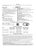
Maintenance:
Unit should be tested at least once a year for the proper operation as follows:
Output Voltage Test:
Under normal load conditions, the DC output voltage should be checked for proper voltage level
(
refer to Power Supply Voltage Output Specifications chart
).
Battery Test:
Under normal load conditions check that the battery is fully charged, check specified voltage both at battery
terminal and at the board terminals marked [+ BAT –] to ensure that there is no break in the battery connection wires.
Note:
Maximum charging current under discharge is 0.7 amp.
Note:
Expected battery life is 5 years, however it is recommended changing batteries in 4 years or less if needed.
CAUTION: De-energize unit prior to servicing. For continued protection against risk of
Fig. 2
electric shock and fire hazard replace fuse with the same type and rating.
Do not expose to rain or moisture.
Fig.
Fig.
Keep power-limited wiring separate from non power-limited.
Use minimum 0.25" spacing.
2a
Door
Green
Lead
Wire
Strap
(from
Enclosure
to Door)
Do Not Touch
Exposed Metal Parts
Bat Fail NC C NO NC C NO Fail
Battery & AC Supervision
Circuit
(power-limited)
115VAC
power mains
non power-
limited
Class 1
Fig. 2c
2b
AC Delay
Opened - 24V
Closed - 12V
SW1
J1
15
+
BAT ---
+
DC ---
Battery connection
(non power-limited)
DC Output to devices
(power-limited)
Battery 1
Battery 2
12VDC Rechargeable Battery
(optional)
12VDC Rechargeable Battery
(optional)
CAUTION: Optional rechargeable stand-by batteries must match
the power supply output voltage setting.
AC
O
p
en
ed
-
24
V
C
lo
se
d
-
12
V
S
W
1
J1
15
A
2
50
V
R
is
k
o
f F
ire
,
R
e
pl
ac
e
F
u
s
es
A
s
M
ar
ke
d
A
C
D
C
B
at
5A
2
50
V
L
G
N
B
a
t F
ai
l N
C
C
N
O
N
C
C
N
O
A
C
F
ai
l
A
C
D
e
la
y


