background image

Содержание 140G17K

Страница 1: ...ERATOR SET 140 KVA 400 HZ 115 200 V AC 3 PHASE with DETROIT DIESEL ENGINE TYPE 8V 71N 5566B Model Numbers 140G17K Truck Mounted Unit 140G17P Trailer Mounted Unit 140G17P With Special Accessories Manufactured by L HOBART BROTHERSCOMPANY POWER SYSTEMS DIVISION j i TROY OHIO 45373 1 U S A ...

Страница 2: ......

Страница 3: ...r mat or dry wood use insulating gloves when dampness or sweat cannot be avoided Keep clothing dry and never work alone 1 Installation and Grounding of Electrically Powered Equipment Equipment driven by electric motors rather than by diesel or gasoline engines must be installed and maintained in accordance with the lational Electrical Code ANSI XFPA 70 and other applicable codes A power disconnect...

Страница 4: ...emoving fuel tank cap completely fill tank because heat from the eouipment may cause fuel expansion overflow Remove all spilled fuel IMMEDIATELY including any that penetrates the unit After clean up fumes away with compressed air open equipment doors and blow Carbon monoxide Engine exhaust fumes can kill and cause health problems Pipe or vent the exhaust fumes to a suitable exhaust duct or outdoor...

Страница 5: ...ck Body Kits C Trailer D Transformer Rectifiers E T R Mounting Kits F Test Box G Revolving Light Description 1 General 2 Orientation 3 Special Features A Protective Monitor System B Pullout Trays C Voltage Regulator D Test Receptacle Connector 1 Ii Jan 22181 1 CHAPTER SECTION PAGE 1 o 1 l l 1 1 1 2 2 2 2 2 2 2 314 l 2 1 1 Contents Page 1 ...

Страница 6: ...r C Engine D Governor E Engine Safety Shutdown System 1 General 2 Air shutoff valve 3 Engine fault sensing devices a General b Emergency stop solenoid valve F Air Cleaner G Control Box 1 Voltage regulator tray a Gantrols b Protection c Components 2 Protective relay tray 1 Contents Page 2 b i TM 528 PAGE 3 3 3 6 6 7 9 9 10 10 10 10 12 I Revised Jan 22 81 ...

Страница 7: ... Diode capacitor and terminal board k Overload relay I Fuses 3 Generator control tray a Resistors 16 b Generator output meters 16 c Meter and I ine switches 16 18 18 18 d Receptacle connect0 r 4 Tray f Manual voltage control H Engine and Generator Control Panel 1 Engine gages and meters a 0 i I pressure gage and diaphragm switch l 2 1 Li I t TM 528 PAGE 12 12 14 14 14 15 15 15 15 15 15 16 18 18 18...

Страница 8: ...lve starting switch b Starter switch c Speed control switch d Light switch e Load contactor control switches f Push to build up voltage switch 5 Excitationtdeenergization relay 6 Fuse 7 Test receptacle connector 8 Speed control cable 9 Cold weather starting aid 10 Terminal boards J Special Engine and Generator Control Panel 1 General 1 2 t l i TM 528 PAGE 18 20 20 20 20 20 20 21 21 21 21 21 21 22 ...

Страница 9: ...ION 1 2 2 Line drop current transformer 3 Ammeter current transformer 4 Locd contactor 5 Diode panel 6 Resistors line drop 7 Overload current transformer 8 Overlood board 9 Indicating light relc 10 Terminal board L Output Terminal Panel Preparation for Use l Generator Set A General B Inspection Check ys and blocking diode l 3 C Output Cables Installation Jan 22 81 Revised TM 528 PAGE 23 23 23 23 2...

Страница 10: ...k 3 Operating the Trailer A General B Operating the Brakes C Drawbar 4 Operating the Generator Set A General 8 Connecting Output Cables C Preparation for Power Delivery 1 Voltage regulator trcy 2 Protective relay tray 1 3 Generator control tray 4 Engine and generator control panei D Normal Engine Starting 1 E Cold Weather Engine Starting Contents Page 6 1 3 3 4 3 4 l 4 1 1 1 1 1 2 2 2 2 2 2 2 3 3 ...

Страница 11: ...r Rectifier Operation 1 Direct current power delivery 2 Simultaneous 28 5 V and 35 V DC power delivery 3 Simultaneous 28 5 V DC and 115 V AC power delivery 4 Simultaneous 35 V DC or 112 V DC Servicing 2 o Maintenance 2 l 1 General 10 10 11 11 11 11 12 12 2 Maintenance Schedule 1 A General 1 B Maintenance Schedule Check Sheet 1 C Time lntemais 1 D Identification of Interval Periods 1 3 Air Cleaner ...

Страница 12: ...2 Battery location and accessibility 3 Battery care 4 Liquid level 5 Cleaning the battery 5 Electrical System 115 V AC A Monitoring Instruments B Indicating Lights C Protective Relays D Wiring and Connections 6 Lubrication A General B AC Generator C Generator Controls D Diesel Engine 1 Lubrication schedule t ontents 5 5 5 s 5 5 5 5 7 7 8 8 8 8 9 9 9 1 i 9 Revised Jan 22 81 Page 8 ...

Страница 13: ... procedures 7 Generator Maintenance 10 13 A Cleaning B Ad i ustment 8 Engine Mcintenance A General 3 Cleaning Ad iustment Test 1 General 2 Testing 13 13 13 2 2 13 13 1 1 1 A Preoperational Test Procedures 1 B Operational Test 4 3 Adjustment 7 A Engine Governor 7 B Generator 8 C Generator Control Adiustments 8 1 Adjust manual voltage co ntrol variable istor 9 Jan 22 81 Revised i Contents Page 9 ...

Страница 14: ...iustrnents E Governor Adiustment F Covernor Speed Control Linkage Adiustment i Adjust switch operating disc position 2 Adjust solenoid linkage 3 Ad just eng ine id le speed 4 Adjust engine governed high speed Troubleshooting Troubleshooting Procedures 1 General 2 Troubleshooting Chart A Description 8 Use of the Troubleshooting Chart 3 Wiring Diagrams II lustrated Parts List c ontents Page 10 2 2 3...

Страница 15: ...rt Part Number Column 3 Nomenclature Column 4 Eff Effective Column 5 Units per Assembly Column Manufacturer s Codes 1 Explanation of Manufacturer s Vendor Code List Parts List 1 Explanation of Parts List Arrangement 2 Symbol s and Abbreviations Numerical Index 1 1 Explanation of Numerical Index Optional Equipent Manufacturer s Literature Jan 22 81 Revised 4 2 4 3 1 4 4 1 5 o 1 6 O Li 1 l 2 l 2 i C...

Страница 16: ...et 1 of 2 Operating Controls and Instruments Sheet 2 of 2 Cold Weather Starting Aid Transformer Rectifiers Typiccl Installation Maintenance Schedule Sheet 1 of 2 Maintenance Schedule Sheet 2 of 2 Air Cleaner Cartridge Replacement Lamp Identification Chart Fuse Identification Chart Engine Lubrication Points Diesel Engine Lubricants Lubrication end Maintenance Chart Symbols and T ime Intervals Opera...

Страница 17: ...elay Tray Assembly Generator Control Tray Assembly Control Box and Internal Components Group Engine Control Panel Assembly Engine Controi Panel Assembly Special Power Module Panel Assembly Output Terminal Panel Assembly Air Cleaner Group Generator Group Red iator and Coo I ing System Engine Group Governor Oil Filter Lines Group Lines Oil Emergency Shut Down Governor Linkage Group Exhaust System Fr...

Страница 18: ......

Страница 19: ... through the manual Each section begins with Page one and the first illustration in each section is Figure 1 Should this manual contain additional information required to cover optional equipment modifications changes and updated designs added after the original manual was released this information will be added at the end of a Section where it would normally be found Added or changed information ...

Страница 20: ... ...

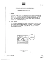
Страница 21: ...been established to define the type of mounting truck or trailer and any special equipment not included with the options I isted below 2 Model Number Ail Hobart generator sets are identified by a model number The units covered by this manual are identified as model 140 G17K which is a truck mounted unit end model 140 G17P which is trailer mounted Figure 1 illustrates a typical nameplate marking 1 ...

Страница 22: ... the available truck options These kits are described and illustrated in TO 110 C Trailer I The optional trailer part number 482158 is covered by an instruction manual TO 106 D Transformer Rectifiers Transfomler rectifiers are available to change the 115 V AC generator output to 28 5 35 and 112 V DC The 28 5 volt unit is covered in TM 597 the 112 volt unit is covered in TM 598 and the 35 vo It uni...

Страница 23: ...Truck Mounted Units This emergency warning iigbt revolves through 3600 Central iy mounted on top of the truck cab it has an on off switch located on the dashboard This option is covered in TO 1 13 1 Jan 22 81 Revised i l l Page 3 4 ...

Страница 24: ......

Страница 25: ...unit NOTE When the generator set is mounted on a truck the rcdictor or FRONT end of the generator set is at the REAR of the truck Operating controls are then on the LEFT or driver s side of the truck When the generator set is mounted on a trailer the radiator is at the drawbar FRONT end 3 Special Features The generator has many special features which are described more fully under the assemblies i...

Страница 26: ... I m I 1 TM 528 TRAILER MOLNTED TRUCK MOUNTED Generator Set Figure 1 f 2 Page 2 i Revised Jan 22 81 ...

Страница 27: ...g two inputs or to one or two aircraft with single input requirements 4 Canopy A sheet metal enclosure identified as a canopy See 1 Fig 2 provides protection for the engine generator and electrical controls Four hinged doors on the left side provide easy access for service and maintenance Two hinged doors near the front on the right side provide access to the engine corn partme nt Panel mounted in...

Страница 28: ...he fan housing the rear bearing is mounted in the forward end of the exciter housing Both of these housings are attached to the main generator stator housing The front end of the rotor shaft extends forward beyond the bearing and is attached to the engine flywheel by a hub and flexible disk coupling assembly A centrifugal radial blade fan part of the hub and coupling assembly draws cooling air ove...

Страница 29: ...7 Diesel engine 2 Air cleaner 8 Lifting yoke 3 Lifting eye 9 Power module contactor panei 4 Access panel output terminals 10 Exciter 5 Engine control panel 11 Generator 6 Control box Generator Set Components Figure 2 1 Ii Jan 22 8 1 Revised l 2 Page 5 ...

Страница 30: ...4 RPM 253 HP Id e speed 800 to 850 RPM Overspeed governor trip 1900 to 2025 RPM Coolant system capacity approx 19 l 2 gals 74 liters Lubricating oil capacity without filters change approx 23 quarts 21 liters Lubricating oil capacity with filters change approx 26 quarts 25 liters Specifications and Capabilities Figure 3 D Governor The mechanical hydraulic governor 4 Fig 4 is identified as a Woodwar...

Страница 31: ...hing a button located on the governor head b Temperature sensing safety switch This switch is mounted in the engine water manifold and is identified as an Alarmstat It is very sensitive to temperature changes and functions to protect the engine against overheating caused by low coolant level broken fan belt etc It sends a signal which activates the shut down solenoid to stop the engine when temper...

Страница 32: ...assembly 2 Shutoff valve housing 3 Overspeed governor 4 Engine governor 5 1Valve shaft 6 Shutdown valve operating solenoid 7 Low coolant and high temperature valve 8 Emergency shutdown solenoid valve Engine Safety Shutdown System t Figure 4 I hi i Revised Jan 22 8 1 Page 8 ...

Страница 33: ...n to warn the operator that the cartridge must be changed The flag is reset unlocked by pushing the reset button 3 located on the bottom of the indicator G Control box The control box 6 Fig 2 is a sheet metal enclosure which houses and provides mounting facilities for generator controls and electrical equipment The box is equipped with three drawer type trays which contain generator output control...

Страница 34: ... circuit into the transistorized pre amp1 ifier cmpl ified and used to drive the magnetic cmplifier The magnetic unpiifier output changes in response to this signal chcnging the field power of the rotary exciter enough to return the generator voltage to its regulated value The ith the vo Itage voltage at which the generator is regulated may be odiusted w adjustment rheostat 2 Fig 6 a Contro is The...

Страница 35: ...ion chassis assembly 7 Receptacle connector 8 Damping circuit gain potentiometer 9 Receptacle connector 0 Damping circuit rate potentiometer 11 Receptacle connector 12 Fuse 5A 13 Fuseholder 14 Receptacle connector 15 Sensing and preamplifier chassis assembly 16 High phase sensing board assembly 17 Reactor 18 Chassis 19 Terminal board Voltage Regulator Figure 6 1 ii Jan 22 81 Revised l 2 1 Page 11 ...

Страница 36: ...elays Trip values for the sensing relays and overload devices are as follows Overvoltage relay trips at 130 V to 134 V UndeNoltage relay trips at 93 V to 103 V Overfrequency relay trips at 415 Hz to 425 Hz Underfrequency relay trips at 375 Hz to 385 Hz Overload device trips at any value over 125 rated load capacity b Protective monitor module The protective monitor 1 is a solid state device with a...

Страница 37: ...age indicating light 12 No 1 resistor 100 Ohm 25 Watt 13 Overvoltage indicating light 14 No 2 resistor 100 Ohm 25 Watt 15 Under frequency indicating light 16 interlock relay fuse 2A 17 Underfrequency indicating light 18 Load contactor circuit fuse 2A 19 Test bank switch 20 Capacitor 6 8 MFD 35 V 21 Terminal board 22 Diode 400 V RV 1 5 A 23 Receptacle connector 24 No 1 plug interlock relay 25 No 2 ...

Страница 38: ... ind icating light The light will remain on until the reset switch 10 is pushed These are press to test type lights in which the lamps bulbs may be tested by pressing the lens holder momentarily d Plug interlock relay The function of the plug interlock relay 24 is to cause the No 1 output load contactor to open in the event the cable plug connector becomes accidentally disconnected from the aircra...

Страница 39: ...kly and easily i Diode capacitor and terminal board A terminal board 21 is used to mount and connect a diode 22 and capacitor 20 into the fuse interlock relay coil circuit Their purpose is to prevent an inductive spike in the 12 V DC circuit from triggering an SCR in the protective monitor module 1 and turning on an indicating light when no fault exists k Overload relay This overload relay 7 is a ...

Страница 40: ...4 These switches are described below The voltmeter has a 3 1 2 inch 89 mm face and the scale is graduated 0 to 300 V The ammeter is also 3 l 2 inch size and is graduated 0 to 500 Ai The crnperage value in each of the three phases may be read on the cmmeter by selecting the desired phase with switch 5 Th ree ammeter current transformers 4 Fig 11 lower the output load current to a lesser value of de...

Страница 41: ...ctor toggle switch Meter selector rotary switch AC Ammeter Voltmeter Frequency meter TO 11 1 2 13 14 15 Generator Control Tray Figure 8 Nylon roller Receptacle connector Tray Resistor 50 Ohm 100 Watt Automatic manual switch Manual voltage control rheostat Rectifier Ii Jan 22 81 Revised 1 l 2 Page 17 ...

Страница 42: ...ntrol box lnstrwnents and controls are protected by a clear Plexiglass panel which is mounted in a frune that extends outward and downward at an angle over the contra I panel Instruments may be observed through the Plexiglass panel and controls may be operated by reaching under the pane I 1 Engine gages and meters a 0 il pressure gage and diaphragm switch The oil pressure gage 7 is a bourdon tube ...

Страница 43: ...t 9 Coolant temperature gage 10 Hourmeter 1 1 Speed control switch 12 DELETED 13 Engine speed control cable 14 Start switch 15 DELETED 16 Terminal board 17 Engine running indicating light 18 Test receptacle connector 19 No 2 contactor indicating light 20 No 1 contactor indicating light 21 No 1 contactor operating switch 22 No 1 contactor operating switch Engine Control Panel 140G17K and 140G17P Fi...

Страница 44: ...ecial is a 12 V DC unit 2 Panel lights Two shielded instrument panel lights 2 provide illumination for instruments and controls during night time operation 3 Indicating lights There are three indicating lights mounted on the control panel a Engine ON indicating light This light 77 gl ows green when the engine is running and engine lubricating oil pressure is holding the diaphragm switch 8 closed b...

Страница 45: ...er single throw toggle switch 5 d Load contactor control switches Each load contactor is controlled by a toggle switch No 1 output contactor is controlled by switch 21 No 2 output contactor is controlled by switch 22 These are three position switches which are spring loaded in the top ON position When placed in the spring loaded ON position the switch provides 115 V AC power directly to a rectifie...

Страница 46: ...int for leads which are connected to selected test points throughout the engine and generator electrical systems Connection and schematic diagrams indicate points at which the lecds are connected This receptacle connector is designed to mate with a test box plug connector It is protected by a dust cap The test box part number 388318 4 is available from Hobart Brothers Company at a nom inal kharge ...

Страница 47: ...connection for a light or small hand tool requiring 115 V 400 Hz power This output circuit is protected by a 20 A circuit breaker 23 3 Emergency stop switch A single throw toggle switch 24 connects power to a solenoid valve in the engine safety shutdown system When activated the valve releases pressure in the engine air valve latching system and causes the air valve to close and stop the engine 4 ...

Страница 48: ...g indicating light 18 Test receptacle connector i7 28 19 No 2 contactor indicating light 20 No 1 contactor indicating light 21 No 1 contactor operating switch 22 No 1 contactor operating switch 23 Circuit breaker convenience output circuit 24 Emergency stop switch 25 Hourmeter operating diaphragm switch 26 Low fuel engine stopped warning light red 27 Push switch low fuel system test 28 Fuse fuel w...

Страница 49: ...ule The power module or contactor pane I Fig 11 is mounted in a horizontal position above the generator below the control box Components of the power module panel assembly are identified as follows 1 Capacitor The function of the three capacitors l which are connected to the generator output leads at the bus bar 3 terminals is to eliminate radio frequency interference before it is transmitted alon...

Страница 50: ......

Страница 51: ...rial such as rags tools shipping papers etc 4 Check fuel coolant and oil hoses and connections for visible leaks Check the ground surface under the unit for evidence of leaks If leaks are discovered correct by tightening hose clamps tube fittings etc as required 5 Check security of attaching and retaining hardware 6 Check f II 0 owing for sufficient quantity a Diesel fuel tank capacity is as follo...

Страница 52: ...k as possible I CAUTION NEVER OFERATE THE ENGINE WITH OIL LEVEL BELOW THE LOW E EL MARK OR ABOVE FULL LEVEL MARK 7 The air cleaner Sect 1 2 Fig 5 is a dry type Be sure there are no papers tapes or other materials covering the air inlet area 8 Check fluid Ievel in the four 6 Volt batteries Fluid should cover plates RIGHT BANK 1 Oil level gage rod 2 Oil filler cap I Engine Oil Gage Rod and Filler Ca...

Страница 53: ...trol box b Loosen cable horn clamps and insert the loose ends of ccble assemblies through cable horns Route to output terminal panel c Each terminal is identified by a letter A B etc indicating the generator output phase Cable lecds are likewise identified by ident if icat ion bands Connect one cable assembly to the upper Tow of terminals Connect the other to the lower row Connect A iecd to A term...

Страница 54: ......

Страница 55: ...ar area may help to prevent a future accident TM 528 2 Read the Truck Owner s Manual 3 Position the side mirrors to give the best possible view to the rear on both sides of the truck 4 Observe and note all blind spots 5 Visually inspect and mentally mste the location of al I controls 6 After making certain of an assured clear operating area drive the truck to become familiar with starting stopping...

Страница 56: ...rake pressure and causes an increase in the effort required to apply the brake and pull the handle into automatically locked position The brake lever handle points directly forward when in locked position The brake is released by pushing the lever inward toward frame C Drawbar When the trailer is not connected to a tow vehicle the drawbar should always be locked in a stowed upright position in the...

Страница 57: ...n they are correctly positioned and have not been tampered with After all controls have been checked at the beginning of an operational shift it is not necessary to repat the checks for each aircraft servicing throughout the shift if it is known POSITIVELY that controls have NOT been tampered with Check the position of generator contra Is as fol lows See F g I ure 1 which illustrates all generator...

Страница 58: ...d e Locd contactor switches 21 and 22 OFF NOTE The engine starting toggle switch 14 is spring locded so that it is normally OFF unless held in ON position D Normal Engine Starting Engine starting steps are outlined below Engine controls ad instruments are illustrated in Fig 1 CAUTION REFER TO OPERATING INSTRUCTIONS IN THE DETROIT DIESEL FERATORIS MANUAL WHEN STPRTING ENGINE FOR THE FIRST TIME 1 If...

Страница 59: ...ating light 20 No 1 contactor indicating light 16 28 4 13 21 No 1 contactor operating switch 22 No 1 contactor operating switch 23 Circuit breaker convenience output circuit 24 Emergency stop switch 25 Hourmeter operating diaphragm switch 26 Low fuel engine stopped warning light red 27 Push switch low fuel system test 28 Fuse fuel warning system test 29 Convenience output receptacle 115 V 400 Hz 3...

Страница 60: ...Load contactor operating system fuse Protective monitor system fuse Protective monitor system reset switch Test bank switch Generator overload relay PROTECTIVE RELAY TRAY 44 Frequency meter 45 AC voltmeter 46 Manual control rheostat 47 AC Ammeter 48 Automatic manual switch 49 Meter switch 50 Line SW itch Gperating Controls and Instruments Sheet 2 of 2 Figure 1 t i 4 Page 6 I 1 m I 1 TM 528 VOLTAGE...

Страница 61: ... FOR A FEW MINUTES IF THE ENGINE FAILS TO START AFTER FOUR ATTEMPTS AN INSPECTION SHOULD BE MADE TO DETERMINE THE CAUSE 3 IF THE EN GINE FIRES SUFFICIENTLY TO DISENGAGE THE STARTER GEAR BUT DOES NOT START RELEASE THE START SWITCH AND ALiOW THE STARTING MOTOR TO COME TO A COMPLETE STOP BEFORE ATTEMPTING TO ENGAGE THE STARTER AGAIN 6 Observe all engine instruments for normal operation 7 Allow engine...

Страница 62: ...mizing nozzle into the air intake housing Continue to push the plunger IN slowly until engine starts 6 When the engine starts release starter switch button 14 Hold starting togale switch in ON position until the green engine light 17 comes ON then RELEASE 7 Adiust speed control 13 for fast idle NOTE If the pump plunger is not all the way IN when the engine starts push it in slowly to LOCKED positi...

Страница 63: ...top ON position until corresponding green indicating light comes ON Release switch It will return to center ON or contactor closed position On 140Gl7P Special use the switch handle 30 to operate cantactor switch Although both contactors will be closed momentarily only the contactor in the circuit which is plugged into the aircraft will remain closed 6 It is recommended that the operator check outp...

Страница 64: ...r varying load conditions H Stop Power Delivery 1 Place load contactor switch es 21 and or 22 in OFF position Indicating light s 19 and or 20 should go OFF ind icating that load contacton are open and load is disconnected from generator set 2 Place speed control switch 11 in OFF position 3 Push speed control 13 IN to full IDLE position against idle stop 4 Disconnect output cables from aircraft Sto...

Страница 65: ...or AC delivery except do not connect AC output cable end do not close AC locd contactor see Para 4 F b For T R operating instructions See TM 597 for 28 5 V DC T R Operating Instructions See TM 599 for 35 V DC T R Operating Instructions See TM 598 for 112 V DC T R Operating Instructions 2 Simultaneous 28 5 V at d 35 V DC power delivery 28 5 V and 35 V DC T Rs may be operated at the same time withou...

Страница 66: ...8 V AC when the DC locd is 500 Amperes If higher DC voltage is needed adiust T R line drop compensation as required Observe AC voltage while making this adiustment to be certain that it does not go TOO HIGH with DC load c During simultaneous continuous operation loads on either circuit are limited only by the capacities of their respective circuits however the combined loads should not exceed the ...

Страница 67: ...a schedule to meet any maintenance requirements C Time Intervals The schedule is based on both hours of operation and calendar intervals These two intervals are not necessarily the same For example in normal operation a lubrication period based on hours of operation will be reached long before the calendar period The calendar period is included to make certain that services are performed regularly...

Страница 68: ...gs etc X Lubricate speed ccntrol and air valve linkage 1 X Drain and refill cooling system a TWICE ANNUALLY Inspect exhaust system X Drain water and sediment from fuel tank X Clean fuel system X Clean engine exterior X Clean air box drains X Clean crankcase ventilating system X Clean blower screen X Refer to Para 6 D 4 Refer to Detroit Diesel Operator s Manual for engine lubrication and maintenanc...

Страница 69: ...dge element cannot be determined because of varying operating conditions Change the cartridge as required See Para 3 below 3 Air Cleaner Cartridge Replacement The filter cartridge requires replacement when the indicator flag Sect 1 2 item 2 Fig 5 becomes locked in top full view position Proceed as follows A Removal 1 Loosen the four wing nuts 1 Fig 2 unlatch clamps 3 and swing the tee bolts 4 outw...

Страница 70: ...R NO CIRCUMSTANCES SHOULD THE CARTRIDGE BE POUNDED OR STRUCK IN THE CENTER TO EFFECT ASEAL _ 2 Lock the cartridge in place by installing the moisture eliminator 7 and clamping in place with the four tee bolts clamps and wing nuts 3 Wing nuts must be tightened evenly crisscrossing from corner to corner After tightening the nuts as tight as possible by hand tighten them two full turns with a small w...

Страница 71: ...ion D Battery Service 1 General Four volt batteries are connected in series to supply 24 V power for cranking the engine and for operating lights engine shutdown safety system etc 12 V DC is topped from the circuit for operation of the 400 Hz generator protective sy em and the hourmeter on 140Gl7P Special 2 Battery location and accessibility On trailer mounted units batteries are mounted in a box ...

Страница 72: ... Control Lamp Industry 313 eating Light Panel Trade No 1 Contactor CLOSED Engine Control Lamp Industry I 120 MB Indicating Light Panel Trade No Fault indicating Protective Re lay Lamp Indusky 1815 Light Tray Trade No Clearance Lights Canopy Lamp Industry 313 Trade No Lamp lden tification Chart Figure 3 1 Sect l 2 Fig 7 Sect l 2 Fig 10 Fuse Identification Chart Figure 4 1 Page 6 t Revised Jan 22 81...

Страница 73: ... SOLUTIONS OR POWDERS NOTE It is especially important to keep the battery at full charge for cold weather operation Add d isti I led water to the battery in freezing temperatures only when the engine is to operate for several hours to thoroughly mix the water and the electrolyte ordunage to the battery may result from freezing 5 Cleaning the battery If the top of the battery is dirty it may be cle...

Страница 74: ... housing C Protective Relays Check operation of all protective relays to make certain that they will function if a fault should occur in the output circuit D Wiring and Connections 1 Check all cables leads and wiring for broken worn and damaged insulation 2 Check all connections for tightness WARNING STOP OPERATIONS AND STOP ENGINE BEFORE TOUCHING EXPOSED CONDUCTORS OR TERMINALS 3 Check the output...

Страница 75: ... 7 are approximate They are based on average operating conditions It may be necessary to lubricate more frequently under severe operating conditions such as low engine temperatures excessively heavy loads and high oil temperatures or intermittent operation However time intervals should not exceed those indicated in the chart without careful evaluation See Para 6 D 4 be ICW 2 Oil specification Oil ...

Страница 76: ...ratory or oil supplier based upon the sample analysis until the most practical oil change period for the particular service has been established The generator set is equipped with an hourmeter to record actu ai engine operating time The ideal time to change oil is soon after a power delivery run when the engine is at operating temperature NOTE If lubricating oil is drained immediately after the un...

Страница 77: ...il filter Engine oil Check doi Iy C 1 Ovetspeed govern AR Air cleaner Change engine oil after each 100 hovrs or as recommended in Para 6 D 4 Change oil filter elements each time engine oil is changed Refer to Engine Manual Jan 22 8 1 Revised Engine Lubrication Points Figure 5 i 2 1 Page 11 ...

Страница 78: ...tain ash but C ias9r CC SC no more than 1 85 Diesel Engine Lubricants Figure 6 1Symbol Time Interva I AR A B C D E S As Required 70 Hours or Dai iy 250 Hours or 3 Months 500 Hours or 6 Months 1000 Hours or 1 Year 1600 Hours or 2 Years Seascna I iy Spring and or Fall Lubrication and Maintenance Chart Symbols and Time Intervals Figure 7 t 2 l Page 12 Revised Jan 22 81 ...

Страница 79: ...BLE SOLVENT B Adiustment The generator itself requires no adiustment Adiustment procedures for generator controls are covered in Section 2 2 8 Engine Maintenance A General The Detroit Diesel Operator s Manual provides detailed maintenance instructions in the Preventive Maintenance Section 8 Cleaning There are several reasons why the engine exterior should be kept clean Dirt on the outside will ent...

Страница 80: ...OLTAGE REGULATOR ALTERNATOR ETC AND ELECTRICAL WIRING 1 4 WARti ING l DO NOT USE A FLAMMABLE SOLVENT 2 SEAL ALLORNINGS SUCH AS OIL FILLER TUBE BREATHER OFENINGS ETC I EXERCiSE CARE TO AVOID INJURY AND DAMAGE TO THE EYES AND SKIN I li h l Page 14 i Rev ised Jan 22 8 1 ...

Страница 81: ...operating the generator set 1 Connect the generator set to a iocd bank and use cables of the same size and length as those to be used in service See l 2 Fig 12 for illustration of output terminal panels 2 Check oil level of engine crankcase 3 Check engine coolant level 4 Check engine V be its 5 Check to be certain that the N lead terminal located on the frame behind the batteries is securely tight...

Страница 82: ...ontactor indicating light 20 No 1 contactor indicating light ia 21 No 1 contactor operating switch 22 No 1 contactor operating switch 23 Circuit breaker convenience output circuit 24 Emergency stop switch 25 Hourmeter operating diaphragm switch 26 Low fuel engine stopped warning light red 27 Push switch low fuel system test 28 Fuse fuel warning system test 29 Convenience output receptacle 115 V 40...

Страница 83: ...LTAGE REGULATGR TRAY VOLTAGE REGULATGR TRAY Fault indicating light 5 Load contactor operating system fuse Proteciive monitor system fuse Protective monitor system reset switch Test bank switch Generator overload relay 44 Frequency meter 45 AC voi tmeter 46 Manual control rheostat 47 AC Ammeter 48 Automatic manual switch 49 Meter switch 50 Line SW itch 38 39 40 PROTECT WE RELAY TRAY GENERATOR CONTR...

Страница 84: ...has waned place speed control switch 11 Fig 1 in ON position and pull speed control cable 13 OUT to FULL SPEED position 8 Operational Test NOTE Tests which must be performed under load require the use of a resistive and reactive load bank Test the following with the generator running 1 Push the press to build up voltage switch 3 momentarily A voltage value should be readable on the voltmeter 45 in...

Страница 85: ... test bank switch 42 in AIRCRAFT position Load contactors should open automatically Apply 24 V DC between interlock terminals N and E or F at each of the output term inal panels Sect l 2 Fig 12 With test bank switch 42 in AIRCRAFT position close load contactors Lee step 7 above3 If interlock relays are good contactors should close and remain closed Return test bank switch to TEST BANK position and...

Страница 86: ...overlocd device should open No 1 load contactor in 3 to 5 minutes Overload indicating light should be turned ON Press reset switch 41 Repeat check for No 2 output 19 Apply a normal load to the generator NOTE Return the generator to normal loaded condition after each of the following tests by pressing reset switch and closing load contactors 20 Check overvoltage protective circuit It should functio...

Страница 87: ...test box Part No 388318 4 This test box is available from Hobati Bro hers Company at a nominal charge Connect the test box plug to the test receptacle 18 Fig 1 Connect a VOM to ihe tip jacks on the test box Perform tests at normal operating speed and NO load Test bcnk switch 42 must be in TEST BANK position The test box has each switch position marked with test condition control settiogs etc and v...

Страница 88: ... i Test Nom inal Vo itage Phase A I 115VAC Phase B j 115 v AC Phase C 115V AC P M Fuse 12 DC FIR OL Battery Voitcge 12 V DC PM Contacts 115VAC No 1 PIR Coil I 24V DC Exciter Input F D approx 17 V DC Regulator Output X V approx 40 V DC No 1 Contactor Phase C OL Contacts No 1 Contactor Switch No 2 PIR 6il No 2 Contactor Phase C No 2 Gntactor Switch Battery Vo itage EDR Full Throttle Sol I I I L 115 ...

Страница 89: ...amping screw when adiustment is completed 2 Adiust generator overload relay ballast resistor The trip point of the overload relay 43 Fig J is determined by the adjustment of one of the bai last resistors 2 shown in Fig 3 NOTE This resistor is identified as 2RES on Schematic Diagram a Loosen slider band clamping screw F Fig 3 b Position slider on resistor 2 to produce 4 0 V DC across the heater ele...

Страница 90: ...ld be made together Switch 4 Fig 4 must be ON Proceed as foIiows aa Adjust the rheostat 2 to point to the length in feet of output ccbie being used Various cable lengths are indicated on a plate mounted behind the rheostat knob 1 bb Adi t h us r eostat 3 to point to the size of cable being used Various cable sizes ate also indicated on a plate behind the rheostat knob cc With generator running no ...

Страница 91: ...must be m e in conjunction with each other because the adjust ment of one may affect the other For example improving the response by adjusting the damp potentiometer 1 may affect the stability as adiusted by the rate potentiometer 2 Pdiust as follows 1 Voltage adjusting rheostat 2 Cable length compensation rheostat 3 Cable size compensation rheostat 4 On off switch line drop compensation 5 Fuse 5 ...

Страница 92: ...ing the screw CLOCKWISE 5 deg to 10 deg past this point for best rate adiust ment ff Tighten cdiusting screw locknuts after adjustment is completed gg Position test bank switch 42 Fig 1 to AIRCRAFT D Basic Engine Adiustments Adiustment procedures applicable to the diesel engine are incivded in the Detroit Diesel Operation and Maintenance Manual E Governor Adiustment Refer to Detroit Diesel Operato...

Страница 93: ...l CLOCKWiSE s RATE Affects stability ADJUSTING SCREW DIRECTION OF ROTATION Regulator will likely be UNSTABLE if cdjusting screw is at either limit of adiustment CLOCKWISE or COUNTERCLOCKWISE From a point near full CO UNTERCLOCK WISE position turn the screw CLOCKWISE until a point is reached where the voltage regula tor abruptly becomes STEADY Best adjustment for the system is usual iy 5 deg to 10 ...

Страница 94: ...o governor lever 77 with pin 16 d install pin 16 and secure with cotter pin Tighten nut 1 NOTE Some cushion is desirable in this adiustment which means that the governor lever should reach full speed position when the plunger is about l 32 to l l 6 inch O 8 to 1 6 mm away from bottoming in the solenoid housing 4 M anuaiiy actuate linkage to make certain it operates freely between no fuel position ...

Страница 95: ...g disc 5 Linkage holding solenoid 6 Clamp 7 Control cable housing 8 Spring 9 Link 10 Pin 11 Control cable extension 12 Nut 13 Bracket 14 Clevis 15 Micro switch 16 Pin 17 Governor lever 18 Washer I i Governor Speed Control Linkage Adjustment Figure 6 Ii Jan 22 8 1 Revised I i 2 2 Page 15 ...

Страница 96: ...tion 4 Ad just engine governed high speed a Start engine All ow it to idle until warmed then place speed control switch 11 Fig 1 in ON position and pull speed control 13 OUT to ful I speed position Press push to build up voltage switch 3 b See Woodward Governor Bulletin in Chapter 6 Use high speed cdjusting screw on Woodward governor to cdiust speed at approximately 1714 RPPA c Position test bank ...

Страница 97: ... Minor troubles may be remedied by the operator however major repairs must be undertaken by experienced mechanics and electricians only D Use of the optional test box is recommended for troubleshooting 2 Troubleshooting Chart A Description The troubleshooting chart lists information under three headings as follows 1 Trouble Symptom and Condition 2 Probable Cause 3 Test Check and or Remedy B Use of...

Страница 98: ...rt are identified by a noun ncme and a Corresponding symbol which allows the user to identify the item more easily on schematjc diagrans It is assumed that wiring and connections in defective circuits have been thoroughly checked before condemning any other components NOTE Reference symbols 5S etc used in the Troubleshooting Chart are identified on Schematic Diagrams 3 Wiring Diagrams All connecti...

Страница 99: ...d old starter to starter overhaul 2 Engine will not start Starter cranks engine normally 3 Engine runs Engine ON indicating light 1G does not glow a Fuel not reaching fuel w w b Mechanical defect in engine fuel system a Lamp bulb defective b Fuse 1FU blown Check to be certain that there is sufficient diesel fuel in tank and that the mechanical shut off valve at tank is open Check for restrictions ...

Страница 100: ... AND CONDITION PROBABLE CAUSE TEST CHECK AND OR REMEDY DIESEL ENGINE CCNTINUED 2 Engine will not D Ambient temperature too D Use starting aid start Starter low for normal engine cranks engine starting procedures normal ly Con t d I 3 Engin e starts and A Air shut down va ive not A Check and repair as follows runs Engine ON being latched open by light glows Engine bellows assembly stops as soon as ...

Страница 101: ... fuse 1 FU or 1 j If green light 1G is ON it diaphragm switch indicates fuse 1 FU and switch TO PS 10 PS are good If not check fuse 4 Fig 5 and switch 8 Fig 5 2 Defective speed control 2 Check continuity of switch switch 7s circuit in ON position Re place switch 11 Fig 5 if defective B Solenoid coil ZSOL im 8 Check ground lead Repair as properly grounded required C Solenoid coil 2S OL defec C Chec...

Страница 102: ...oltage replace cedures Engine push to build up voltage running at governed switch 3 Fig 5 speed 3 Defective excitation 3 If voltage was present at pin deenergizaticn switch 7PLG in test 2 A above EDR replace excitaticn deenergi zafion relay 1 Fig 5 C Defective vol tage regula C Place automatic manual switch tor REG or automatic 1s in MANUAL position manual switch 1s Press switch 2PB If voltage is ...

Страница 103: ...witch 2 2 15 2PB is held then Fig 6 I is being actuated properly drops when switch check continuity 0 If switch is is released defective replace 8 Defective contacts in 5 Jumper terminals 1 and 3 on EDR excitation deenergizaticn If voltage is now maintained re relay EDR place relay 1 Fig 5 4 Generator voitage A Defective voltage regula A Refer fo Manual TM 759 far tesl too high too low tor REG pro...

Страница 104: ...circuit in generator A Check field resistance lf revolving fields IFLD field is open circuited repair or replace 8 Open circuit in generator B Check stator windings for stator windings GEN open circuit Repair or replace as required 2 Generator over heats A Improper ven ti lat ion A Check for foreign mater ial in ventilbticn system Provide adequate ventilation B Loose connections B Check and tighte...

Страница 105: ...ier C Defective load contactor C Check resistance of ccntactcr coil 1 LC or 2LC coil between terminals Xl and X2 If coil is open replace complete load contactor 6 or 7 Fig 6 3 Contactor closes A Cable plug connector not A Make certain that plug and but opens immed properly connected to air receptacle are good and that all iate ly upcn re craft receptacle connector terminals make good contact lease...

Страница 106: ...ts has functioned normally to determine what fault caused to open load contactor protective monitor to function Correct the conditicn which caused shutdown E Cable plug accidentally E Reconnect cable and resume disconnected from aircraft operation 5 Ccntactor closed A Defective lamp A Check lamps 19 and 20 Fig indicating light 5 and replace if defective 2G or 3G does not operate when con B Defecti...

Страница 107: ... plug boxes 8 Defective micro switch B By pass each switch with a 1PBMS or 2PBMS in iumper wire If engine wil I plug box start remove iumper wires cne at a time to locate defec tive switch Replace defective switch If engine wil I not start see truck manua I CAUTION DO NOT OPERATE TRUCK WITH ANY SAFETY DEVICE JUMPERED 1 I Troubleshooting Chart Sheet 9 of 9 1 Jan 22 81 Revised Figure 1 3 1 L Page 11...

Страница 108: ...Receptacle connector 5 On Off swi tch I ine drop compensation 15 Sensing and preamplifier chassis 6 Line drop compensation chassis assembly assembly 7 Receptacle connector 16 High phase sensing board assembly 8 Damping circuit gain potentiometer 17 Reactor 9 Receptacle connector 18 Chassis 10 Damping circuit rate pote ntiometer 19 Terminal board Voltage Regulator t Figure 2 3 1 Page 12 Revised Jan...

Страница 109: ...ing light 22 IO Reset switch 23 11 Undervoltage indicating light 24 12 No 1 resistor 100 Ohm 25 Watt 25 13 overvoltage indicating light Protective Relay Tray Jan 22 8 1 Revised Figure 3 No 2 resistor 100 Ohm 25 Watt Underfrequency indicating I ight Interlock relay fuse 2 A Underfrequency indicating light Load contactor circuit fuse 2 A Test bank switch Capacitor 6 8 MFD 35 V Terminal board Diode 4...

Страница 110: ... Instruction plate 11 Tray Line selector toggle switch 4 1 2 Resistor 50 Ohm 100 Watt 5 Meter selector rotary switch 13 Automatic manual switch 6 AC Ammeter 14 Manual voltage control rheostat 7 Voltmeter 15 Rectifier 8 Frequency meter Generator Contrbl Tray j i 5 1 Figure 4 I Rev ised Jan 22 81 Poge 14 ...

Страница 111: ...t 9 Coolant temperature gage 10 Hourmeter 11 Speed control switch TM 528 I6 28 14 13 12 DELETED 13 Engine speed control cable 14 Start switch 15 DELETE D 16 Terminal board 17 Engine running indicating light 18 Test receptacle connector 19 No 2 contactor indicating light 20 No 1 contactor indicating light 21 No 1 contactor operating switch 22 No 1 contactor operating switch Engine Control Panel Fig...

Страница 112: ...hm 7 5 Watt No 2 6 Load contactor No 2 7 Load contactor No 1 11 Terminal board 8 term 2 Diode blocking No 2 18 light Grommet circuit 3 19 Terminai board 20 term Diode biocking No 1 light circuit 20 4 Diode panel Overload board No 2 5 rectifier Light relay No 1 No 6 1 Light relay No 2 7 Overload board No 1 Power Module Con tactor Pane I Figure 6 3t1 Page 16 Revised Jan 22 81 s ...

Страница 113: ...ranged as fol lows Section 7 introduction Section 2 Manufacturer s Codes Section 3 Paris List Section 4 INumerical Index 4 Explanation of Parts List A Contents The parts list contains a breakdown of the equipent into assemblies sub assemblies and detail parts All parts of the equipment are listed except 1 Standard hardward items attaching parts such as nuts screws washers etc which are available c...

Страница 114: ...ENCLATURE column 3 NOMENCLATURE Column The item identifying name appears in this column The indenture meihcd is used to indicate item relationship Thus components of an assembly are listed directiy below the assembly and indented one space Vendor codes and part numbers for purchased parts are shown in this colunn Hobart modification to vendor items is also noted in this column 4 EFF Effective Colu...

Страница 115: ...oes not havela venda code the full name of the manufacturer will be listed in the nomenclature column C ODE VENDa S NAME AND ADDRESS 00543 Kobertshaw Controls Company P 0 Box 3775 Anaheim California 92803 01428 Supericr Ball Joint Ccrpcration 1202 S Quality Drive P O Box 227 New Haven Indiana 46774 01537 Motorola Communications and Electronics Inc 4500 West Augusta Blvd Chicago Illinois 60651 0223...

Страница 116: ...Uncasville Connecticut 06382 Cole Hersee Company 20 Old Colony Avenue Baton Massachusetts 02127 S pague E lectr ic Company 300 W National Vandaiia Ohio 45377 Bendix Corp Brake and Steering Division 410 W Bendix Drive South Bend Indiana 46619 Crane Company 4100 S Kedzie Avenue Chicago ill inois 60632 Westinghouse E lectric Corpcration Lamp Division Hcult Kcad P O Box 1312 Fairmont West Virginia 265...

Страница 117: ...ch Company Columbia West End Avenues Lancaster Pennsylvan ia 17604 Cutler Hammer Inc Power Distribution Control Division 4201 N 27th Street Milwcukee Wisconsin 53216 De tch E iectr ic Company 2133 Chaifant Street Pittsburgh Pennsylvania 15221 Imperial Eastman Ccrpcration 6300 W Howard Street Chicago Illinois 60648 Waiter Kidde and Co Inc Belleviile New Jersey N coma H offman Bear ings C crpcrat io...

Страница 118: ...Ge nera I Motcrs C crporat ion 1300 N Dart H ighway FI int Michigan 48556 Atlantic India Kubber Works Inc 571 W Polk Street Chicago Illinois 60607 Bussman Manufacturing Division of McGraw Ed ison C ompany 2536 W U n ivers ity Street St Lcuis Missouri 63017 Detroit D iese I E ng ine D iv is ion Genera I Motors C crpcrat ion 13400 W Outer Drive Detroit Michigan 48239 Diaiight Ccrpaation 60 Stewart A...

Страница 119: ...inois Harvey Hubbe Ii Inc State Street and Bostwick Avenue Br idge pcxt C onnect ic ut 06602 KD Lamp Division The Duplan Ccrpcrction 1910 E lm Street Cincinnati Ohio 45210 Marlin Rockwell Company Division Thompson Kamo Wooidridge Inc 1002 C hand ler Street Jamestown New Ycrk 14701 American Machine Foundry Company Potter Brumfield Division 1200E Broadway P G Box 522 Princeton Indiana 47570 Premier ...

Страница 120: ...o Avenue Chicago Illinois 60651 Holub Industries Inc 413 De Kaib Avenue SF amcre Illinois 60178 E lectr ic Auto Lite Company Lebanon Road Cincinnati Ohio Square D Company Indlstriai Controller Division 4041 Ncrth Richards Street Milwaukee Wisconsin 532 12 Idea I C crporat ion 435 Liberty Avenue Brooklyn New Ycrk 11207 S immons Fastener C crpcxat ion 1761 N Brcadway Albany New Yak 12204 Sarkes Tarz...

Страница 121: ...yweil Inc Buildings Controls Components Group Micro Switch Division Free port I1I inois Willard Manufacturing Company Miamisburg Ohio Anch cr lndustr ies inc 1725 London Read C leve land Oh io 44 122 United Manufacturing C ompany Dobeckmun Avenue Cleveland Ohio 44102 Everhot Rcducts Company 2003 09 W Carroll Ave Chicago Illinois Kim H otstart Manufactur ing Company 917 W Broodway Spokane Wash ingt...

Страница 122: ...SS The lenz C ompa ny 3301 Klepinger Rd P O Box 1044 I Dayton Ohio 45401 E T C Inc 990 E 67th Street Cleveland Ohio 44703 98991 Wcfcester Va Ive Company lric 16 Parker Street Wcrcester Massachusetts 01610 I 1 I I 4 2 Page 8 Revised Jan 22 81 1 ...

Страница 123: ...lustrated A or AMP ampere AC alternating current AR as required DC direct current Fig Figure hd head hex hexagcn Hz Hertz cycles per second I D inside diameter IN inch KVA kilovolt ampere MFD microfarad No number NHA next higher assembly PRV peak reverse voltage PSI pounds per square inch Ref reference the item has been listed previously TM Technical Manual T R transformer rectifier V volt when us...

Страница 124: ... 4 1I Generator Set Figure 1 14 3 TM 528 I i Revised Jan 22 81 i Page 2 ...

Страница 125: ...SET W ITHO UT CAN OPY For Details see Fig 3 TRUCK ASSEMBLY Optional INCLUDES TRUC K BODY 482 150 AND CHOICE OF TRUCK CHASSIS CHEVRO LET CS 51403 403793 FORD F 500 403769 GMC CS 5 1403 404092 DOD GE D 500 402925 FOR DETAILS CC TRUCK BODY AND TRUCK CHASSIS SEE SUPPLEMENT MANUAL NO TO 1 10 A TRAILER ASSEMBLY Optional FOR DETAILS OF TRAILER ASSEMBLY SEE SUPPLEMENT MANUAL TO 106 BC SW ITCH LOW FUEL LEV...

Страница 126: ...TM 528 Canopy Assembly 1 Figure 2 I 14 3 Page 4 Revtsed Jai 22 81 ii ...

Страница 127: ...AR AND RIGHT FRONT FRONT 13 387 839 14 387840 STOP DOOR LEFT FRONT e STOP DOOR RIGHY FRQNTAND LEFT REAR 1 5 16 17 18 19 20 21 22 23 24 25 26 27 28 387799 385474 387816 3 878 3879 8 8 387845 387847 lOOGH 117 7J 422 O lOOGH 121 lOOGH 118 3 87893 387823 387829 6FW 343OA 3 CANOPY TOP PANEL ACCESS TERMINAL PANEL PANEL CENTER RIGHT SIM PANE 1 CENTER LEFT SiDE STIFFENER PANEL PANEL RIGHT REAR PANEL BOTTO...

Страница 128: ...t 4 3 Page 6 IO 9 8 Generator Set Without Canopy 1 Figure 3 I Revised Jan 22 8 1 TM 528 ...

Страница 129: ...KET CAPSULE PUNCTURING TOOL BOX ASSEMBLY CONTROL Fox details see Fig 4 PANEL ASSEMBLY ENGINE CON TROL For details see Fig 9 0 PANEL ASSEMBLY ENGINE CON TROL For details see Fig 10 C PANEL ASSEMBLY POWER MODULE For details see Fig 11 PANEL ASSEMBLY OUTPUT TERMINAL For details see Fig 72 AIR CLEANER GROUP For details see Fig 13 GENERATOR GROUP For details see Fig 14 RADIATOR AND COOLING SYSTEM For d...

Страница 130: ...L ...

Страница 131: ... ASSEMBLY VOLTAGE I REGULATOR For details see Fig 5 2 3877698 z TRAY ASSEMBLY PROTECTIVE RELAY For details see Fig 6 3 388327A 5 TRAY ASSEMBLY GENERATOR CONTROL For details see Fig 7 4 NoNumber CONTROL BOX AND INTERNAL COMPONENTS GROUP For details see Fig 8 i 1 Jan 22 81 Revised EFF TM 528 UNITS AFIG REF 1 4 3 Page 9 ...

Страница 132: ...m I TM 528 4 3 Age 10 Voltage Regulator Tray Assembly Figure 5 Revised Jan 22 81 i ...

Страница 133: ... VOLTAGE REGU TOR For NHA see Fig 4 4303918 1 REGULATOR VOLTAGE For deiail s see TM 759 386884 1 TRAY ASSEMBLY 370382A HANDLE 384913 384912 8 SLIDE TRAY LEFT SLIDE TRAY RIGHT 382818 W 11250 SCREW TRAY FASTEN ING WASHER SCREW RETAIN ING t 386890 TRAY I I TM 528 LN ITS A REF 1 Jan 22 81 Revised 4 3 i Page 11 ...

Страница 134: ...I I TM 528 i 6 14 I5 16 31 32 Protective Relay Tray Assembly iI Figure 6 I t 4 3 Revised Jan 22 81 Page 12 i ...

Страница 135: ...1 BRACKET RELAY MOUN TIN G REL4Y PLUG INTERLOCK t V77342 No KAP 14DG RE LAY OVERVOLTAGE RE LAY UN DER VO LTAGE RELAY UNDERFREQLENCY RELAY OVERFREQUENCY RELAY OVERLOAD SWITCH TOGGLE TEST BANK V73559 No 2GK71 73 DELETED BRACKET SWITCH MOUNTING TERMINAL CONNECTOR HOUSING CONNECTOR BOARD ASSEMBLY PROTECTIVE MON ITOR WASHER SHOULDER FIBER MOUNT SHOCK PROTECTIVE MONITOR BOARD CAPACITOR 6 8 MFD 35 V V141...

Страница 136: ...14 3 Page 14 TM 528 Revised Jan i2 81 ...

Страница 137: ... V71400 No HKP HH SWITCH PUSH RESET VO4009 No 3391 LIGHT INDICATING V72619 No VM911 6A LAMP INCANDESCENT voaioa No 1815 PLATE IDEN TIFICATION OVERVOLTAGE P IX IDENTIFICATION UN DERVOLTAGE PtiTE IDENTIFICATION OVERFREQUENCY PLATE IDEN TlFiCATlON UNDERFREQ UENCY PLATE IDEN TIFtCATiCN OVER LOAD PLATE INSTRUCTION PRESS TO RESET PLATE IDENTIFICATION TRAY TRAY ASSEMBLY HANDLE SLIDE LEFT SLIDE RIGHT SCRE...

Страница 138: ...TM 528 I j 3 Page 16 Generator Control Tray Assembly Figure 7 j Revised Jan 22 81 i ...

Страница 139: ...SELECTOR VO4009 No 81579 FT EFF TM 528 u 4 ITS A Y RFF 1 1 1 SWITCH TOGGLE V73559 t No 2GL61 TABS PlAlE INSTRUCTION SWITCH TOGGLE AUTO MATIC MAN UAL 04009 No 80950 BRACKET SWITCH RESISTOR 50 OHM 1 00 WATT V44655 No 0959 RESISTOR 25 OHM 100 WATT v44655 No 0958 BRACKET RESISTOR V44655 No 12 KNOB RHEOSTAT V44655 No 5150 PLATE IN STR UCTlOt j FIE LD RHEOSTAT RHEOSTAT VARIABLE V44655 MODEL L 1 1 1 1 1 ...

Страница 140: ...TM 528 I 4 3 Page ia Revised Jan 22 81 ...

Страница 141: ...8 NOMENCIATURE HOBART PARTNO 1234567 384912 SLIDE RIGHT 382818 SCREW TRAY FASTENING W 11250 1 WASHER SCREW RETAIN IN G 385785 RAY 388328 25 NAMEPLATE IDENTIFICATION EFF I L TM 528 UNITS Fer A SSY 1 Jan 22 81 Revised i 4 3 Page 19 ...

Страница 142: ...II 12 6 3 Page20 2 Control Box and Internal Componentsq oup Figure 8 i Revised Jan 22 81 ...

Страница 143: ...NDESCENT VO8108 No 1251 CLAMP WIRE PIASTIC V81074 No EC 6 CLAMP WIRE PLASTIC V81074 No EC 8 CONNECTOR PLUG VOLTAGE REGULATOR IRAY 02660 No MS 3106A 22 145 CLAMP CONNECTOR VO2660 No AN 3057 12 CONNECTOR PLUG PROTEC TIVE RELAY TRAY VO2660 No MS 31 A 28 12s CLAMP CONNECTOR VO2660 No AN 3057 16 CONNECTOR PLUG GENERATOR CONTROL TRAY VO2660 No MS 3lO6A 28 16s GROMMET PLASTIC V77379 No 9235 TERMINAL BOAR...

Страница 144: ...j T 7 m 1 TM 528 f 3 Page22 Engine Control Panel Assembly i Figure 9 ii Revised jan 22 81 ...

Страница 145: ...11 BRACKET SOCKETMOUNT 1 ING SWITCH TOGGLE V91929 No 312TSl 59 SWITCH PUSH VO4009 No 3391 GL CAP DUST VO2660 No 9760 28 CONNECTOR RECEPTACLE TEST VO2660 No MS 3102A 28 125 SWITCH TOGGLE V27191 No 7320K3 SWITCH PRESSURE V74400 No M 4006 TEE PIPE V79470 Nd 3700 X 2 PUMP ASSEMBLY COLD WEATHER STARTING AID V72582 N o 5230535 For de tails see Detroit Diesel Parts Book for V 71 engines HOWMETER V26992 M...

Страница 146: ...f 3 Page24 I m 1 TM 528 Revised Jdn 22 81 ...

Страница 147: ...NDldATlNG GREEN 24 V DC V72619 No 26 1310 1192 301 A B LAMP INCANDESCENT VO8108 No 313 A B TERMINAL BOARD V98410 No 38012 3820 A B FUgHOLDER V71400 TYPE NO HKP HH Ad FUSE CARTRIDGE TYPE V71400 TYPE AGC 10 AMP A B LIGHT INSTRUMENT PANEL V13445 No DL 21 0 L4MP INCANDESCENT VO8108 No 1257 AJ LIGHT IN D ICATING GREEN 115 V AC V72619 No 26 131 1 1192 301 A B LAMP INCANDESCENT VO8108 No 120MBe A B PANEL...

Страница 148: ...I m I I TM 528 I Erg ine Control Panel Assembly Specl pl Figure 10 4 3 j ReQisedJan 22 8 1 Page26 ...

Страница 149: ...SWITCH TOGGLE V91929 No 3 12TS l 59 SWITCH PUSH VO4009 No 3391 0GJ CAP DUST VO2660 No 9760 28 CONNECTOR RECEPTACLE TEST VO2660 No MS 3102A 28 125 SWITCH TOGGLE V27191 No 7320K3 SW ITCH PRESSURE V74400 l No M 4006 TEE PIPE V79470 Nq 3700 X 2 PUMP ASSEMBLY COLD WEATHER STARTING A ID V72582 N o 5230535 Far details see Detroit D ieseI Parts Book fcx V 71 engines HOURMETER V01537 Model No HM 12 GAGE TE...

Страница 150: ...4 3 i Revised Jan 22 8 1 TM 528 I Page28 ...

Страница 151: ...8012 3820 FUSEH OLDER V77400 TYPE NO HKP HH D FUS CARTRIDGE TYPE V77400 TYPE AGC 10 AMP LIGHT INSTRUMENT PANE L V74400 No MI 3216 UMP INCAN DESCENT l V74 400 No 3271 LiGHT IND ICATING GREEN l 115 V AC V72619 No 26 1370 1192 301 LAMP INCANDESCENT VO8108 N 0 12oMB PANEL ENGINE CONTROL CONNECTOR RECEPTACLE TWIST LOCK V74545 No 7582 C WCU IT BREAKER V81487 l No QOB 120 120 V 20 A BRACKET CIRCUIT BREAK...

Страница 152: ...m I 1 TM 528 Power Module Panel Assembly Figure 11 I f 3 Page30 Revised Jcin22 81 ii ...

Страница 153: ...BUS BAR CONTACTOR TO TRANS PHASE A BUS BAR TRAN SFORMER 1 BUS BAR CON TACTOR PHASE C BUS BAR CON TACTOR PHASE B BUS BAR CONTACTOR PHASE A CAPACITOR 0 1 MFD 500 V AC DC V90201 No B 205143 RECTIFIER SILICON 04713 No SCAl0270 1 Deleted Deleted IN SULATOR RESISTOR RESISTOR 25 OHM 25 WATT V44555 No 02OOC INSUL4TOR RESISTORS CONTACTOR 3 p st V74063 No A 874C RESISTOR 16 6 OHM 7 5 WATT TOLERANCE 1 MAX WO...

Страница 154: ...k 3 Page32 I l Rebised Jan 22 81 ...

Страница 155: ...A Vl9816 No IN4820 TERMINAL BOARD V88223 No 441 8 TERMINAL BOARD V88223 No 441 20 GROMMET PLASTIC PANEL POWER MODULE MOUNT RUBBER V89373 No B 323 To mount capacitors to power module Required on 55566 Var 8 only CABLE ASSEMBLY POWER ELECTRI CAL No 101 ph ase Al No 1 bad Ccntactor to phase A No 1 Output Terminal Panel Na 102 Phase Bl No 1 Load Contactor to phase B No 1 Output Terminal Panel No 103 P...

Страница 156: ...D m I TM 528 4 3 Page34 Output Terminal Panel Assembly Figure 12 Revised Jan 22 8 1 i ...

Страница 157: ... PANEL ASSEMBLY OUTPUT TERMINAL For NHA see Fig 3 NUT PLAIN HEX l 4 20 WASHER LOCK l 4 IN WASHER FIAT l 4 IN WASHER INSULATING V89873 No E6147Dl BUSH IN G IN SULATIN G V28987 No 300 A STUD l 4 20 NUT PLAIN HEX 3 8 16 BUS BAR TERMINAL BUSH IN G IN SULATOR BUSH NG INSULATCfi SLEEVE SCREW CAP HEX HD 3 8 16 X 2 IN WASHER LOCK 3 8 IN WASHER FIAT 3 8 1N WASHER IN SULATIN G PANEL OUTPUT TERMINAL TM 528 E...

Страница 158: ...Air Cleaner Group Figure 13 d 3 TM 528 I I Revised Jan 22 8 1 ii Page 36 ...

Страница 159: ...NER GROUP For NHA see Fig 3 AIR CLEANER KIT INDICATOR SRVICE V2 1585 No L 14440 25 INSTALLATION KIT INDI CATOR V21585 No L i4439 CLAMP HOSE V21585 No L 4690 12 ELBOW RUBBER V21585 No A 15094 3 REF 1 i 1 2 AIR CLEANER MOISTURE ELIMINATOR V21585 No D 42970 15 CARTRIDGE FILJER V21585 No P 40 HOUSING AIR CLEANER PIFE AIR CLEANER GASKET PIPE FL4NGE SUPPORT ASSEMBLY PIPE 1 I I t Jan 22 8 1 Revised i 4 3...

Страница 160: ...TM 528 Generator Gmup Figure 14 1 4 3 Page38 i Revised Jan 22 81 ...

Страница 161: ...URE EXCITER 1 W 10874 1 DIODE 35 AMP POS V84970 No ST460P 3 W 108J5 1 DIODE 35 AMP NEG V84970 l No ST46QN 3 481397 KEY hkHlNE EXCITER 1 No Nurher HOUSING ASSEMBLY EXCITER 1 lOCNH 2 POLEPKE EXCITER 4 lOONH 3 INSULATION EXCITER 4 DATA 3 169 WINDINGS EXCITER 1 SET 384183 l l H OUS1NG EXC iTER 1 48012 b1 HOUSING FAN 1 16DA 4249 11 RIN G RETAINER EXCITER LOCATING v79 136 No 5700 175 1 W l 0072 48 BEARI...

Страница 162: ...I m I 1 TM 528 Rediator and COG 1ingSystem Figure 13 I 4 3 Page40 Revised Jan 22 81 ...

Страница 163: ... 3 8 IN I D CLAMP HOSE V97576 No J340 REF 1 2 24 IN 2 ADAPTER STRAIGHT TUBE TO HOSE V30327 No KA06 05NS ADAPTER STRAIGHT TUBE TO HOSE V79470 No 48 X 6 ELBOW PfpE TO TUBE V79470 49 X 68 6 X 6 DE LETED HOSE RUkER WIRE INSERT 1 IN I D 43 IN TOTAL CLAMP HOSE V66295 No C2OP 43 BRACKET SUPPLY HOSE PIPE SlEEk 3 4 IN NPT X 3 IN LG ELBOW PIPE STREET 90 DEG 3 4 IN NPT HO RUBBER TOP 2 l 4 IN I D 38 IN TOTAL ...

Страница 164: ...I m 1 TM 528 14 3 Revised Jan 22 81 I Page42 ...

Страница 165: ...RE HOBART PART N 0 1234567 UNITS EFF AT 387679 402257 i 387699 50GHP 90 402247 384486 56555 351547 HEAD RADIATOR GASKET BASE RADIATOR RAIL SIDE CORE RADIATOR STRIP REINFORCiNG TUBE NEOPRENE OVERFLOW l l LENGTH 55 LABE L CAUTION FAN i 2 1 Jan 22 81 l vised 4 3 Page43 ...

Страница 166: ...I OIL PRESSURE GAGE TM 528 GAGE 4 Engine Group Figure 16 3 age 44 1 ii March 24 95 Revised ...

Страница 167: ...NOR OIL FILTER FILTER FUEL For details see Detroit Diesel Parts Book STRAINER FUEL For details see Detroit Diesel Parts Book I BRACKET FILTER LINKAGE GOVERNOR SPEED CONTROL For details see Fig 18 Items 8 through 15 have been deleted 403264 l No Number 481351 l 481351 2 OVERSPEED GOVERNOR SOLENOID SHUT DOWN For details see Detroit Diesel Parts Book FUEL AND OIL LINES GROUP TRUCK MOUNTED UNITS For d...

Страница 168: ... 4 3 m I I TM 528 Revised Jan 22 81 Page46 ...

Страница 169: ...FT SiDE 7 l 4 IN I D HOSE RUBBER BREATHER PIPE EXTEN S ON RIGHT SIDE l 1 4 IN I D 36 IN CLAMP HOSE 1 to l 3 4 IN SIZE V 295 No C2OP CIAMP HOSE l 1 2 to 2 l 2 IN SIZE V66295 No C32P EXHAUST SYSTEM For details see Fig 19 SUPPORT ENGINE REAR BUSHING PIPE TEMPERATURE GAGE 3 4 TO l 2 IN N PT CAPACITOR VOLTAGE REG ULATOR 0 1 MFD V90201 B 206022 ENGINE DIESEL V72582 8V 7lN MODE L 7083 7000 For details se...

Страница 170: ..._ j I 8 m I 1 TM 528 TO CONNECTOR ON ENGINE i BLOCK 1 _ PObottomof governor oil filfer Governor Oil Filter Lines Group Figure 17 I P e 48 Revised Jan 22 81 j ...

Страница 171: ...RE HOBART AIRLINE PER ITEM NO PART NO PARTNO 123456 ASSY 17 480890A GOVERNOR OIL FILTER LINES 1 56550 GROUP For NHA see Fig 16 REF HOSE SIZE No 6 15 2 404057 2 APAPTER TUBE TO HOSE SWIVEL ELBOW 2 I 1 March 24195 Revised 4 3 Page 49 ...

Страница 172: ...I m 1 TM 528 j 3 Governor Linkage Group 1 Figure 78 4 Revised Jab 22 81 Page52 ...

Страница 173: ... 3 LINK EZLLCRAN K TO SOLE NOID 10 W 9476 14 ROD EXTENSION IDLE AD JUSTIN G 11 5cw 794 12 1OOGH 410 13 382213 14 J 366 15 1OOGH 42 1 16 W l 1269 3 17 40211 9 4 ia 19 20 21 22 1 23 24 16DA 619 W 11245 5 381914 COUPLIN G CONTROL ROD PIVOT ADJUSTING ROD BELL CRAN K CLAMP PUSH PULL CONTROL BRACKET PIVOT NUT HEX SELF LOCKING SCREW CAP HEX HD l 4 20 X 3 4 IN SPACER BRACKET WASHER FLAT BRASS l 4 IN CONaR...

Страница 174: ...TM 528 Exhaust System Figure 19 I I 14 3 Page54 Revised Jan 2 3 1 1 ...

Страница 175: ...08 382809 lOOGHP 1158 lOOGHP 1157 382798 382834 404151 6FW 2 114 3 382827 382828 lOOGHP 1158 lOOGHP 1 ln CLAMP MUFFLER PIPE ASSEMBLY EXHAUST LEFT SIDE CLAMP PIPE PIPE UPPER LEFT PIPE LOWER LEFT GASKET FLANGE FIAN GE MAN IF0 LD CONNECTION PIPE ASSEMBLY EXHAUST RIGHT SIDE CLAMP PiPE PIPE UPPER RIGHT PIPE LOWER RIGHT GASKET FLANGE FLANGE MAN IFOLD CONNECTION STRAP CANOPY RE IN FORCE MENT CLAMP EXHAUS...

Страница 176: ...TM 528 d 3 Page56 Frame Group Figure 20 I I Revised Jan 22 81 I ...

Страница 177: ...BER v73823 No 314c Rohu m RUBBER v92850 No AGW 1501 COVER POWER MODULE END COVER POWER MODULE TOP SUPPORT CONTROL BOX AND BATTERIES INSULATOR STAND OFF SUPPORT EN G INE REAR YOKE LIFTING e FRAME BRACKET MTG FUEL LINES o BRACKET MTG FUEL LINES CL 1MP FUEL LINES TM 528 UNITS EFF A REF 1 10 6 2 1 1 1 REF 1 1 1 2 3 WASHER INSULATOR For Neutrai Terminal on Control Box Support 2 BUSHING For Neutral Term...

Страница 178: ......

Страница 179: ...MBER A 25 ADAPTER PIFE TO TUBE AIR CLEANER AIR CLEANER GROUP AW 626 B 93 BELLOWS ASSEMBLY CONTROL BOX DATA 3169 DDW 495 l DW 1704 DW 6080 ENGINE GROUP 2 EXHAUST SYSTEM FILTER FUEL FILTER GOVERNOR OIL FRAME GROUP FW 1312 FW 2267A GENERATOR GROUP Jan 221 81Revised FIGURE FIGURE ITEM NUMBER PART NUMBER ITEM NUMBER 12 4 20 O 17 7 13 o 3 7 13 O 20 O 1l 30 16 17 4 4 8 O 14 13 19 1 12 5 9 18 lo 18 3 10 1...

Страница 180: ...1 W 10886 3 W 1088 4 5 15 5 17 4 8 4 9 5 6 7 4 W 10891 2 17A I W 10891 4 15 7 W 10891 8 17 3 F 10892 2 17 8 W 10893 0 17A 2 15 5 ihrne rical Index 4 4 Page2 PART NUMBER ky 10910 O W l 1097 8 w 11166 1 W l 1166 3 W l 1242 5 W 11242 10 W l 1245 5 W l 1250 W l 1254 4 W l 1254 6 W l 1269 3 W l 1278 5 W l 1280 2 W 2974 K W 2974 L W 7814 5 N 799J 203 W 8095A 9 W 8 105 4 W 9234 55 W 9476 14 w 9549 19 w 9...

Страница 181: ...5 10 30 16 24 20 8 19 10 19 15 19 9 19 14 13 9 1 4 5 1 4 11 14 12 lo 32 15 13 7 6 11 31 7 12 6 5 9 2 10 2 6 2 11 26 9 4 10 4 6 3 9 3 10 3 11 27 PART NUMBER 16DA 4249 11 16DA 4253 1 16DA 5082 ItDA 619 3OFP 801 30GH 1262 30GH 417 30GH 718 30GH 719 30GH 720 30GH 721 30GH 722 30GH 723 30GHP 391 351541 363771 5 370382A 380522 l 381439 381910 381914 382206 382209 382212 3 382213 382217 382218 382262 382...

Страница 182: ...6 8 16 14 16 9 16 13 14 19 14 7 14 14 14 4 20 9 15 30 11 4 11 7 8 13 8 13 5 3 6 41 7 24 5 3 6 41 7 24 6 27 7 19 11 33 11 32 11 6 11 5 11 3 11 2 11 T 15 12 385449 385450 385474 385579 385580 385664 385679 385784 385785 386751 386829A 1 386884 386890 386921 387646 387654 387658 387675 387679 387698 387699 387715 387725 387736A 387738A 3877698 2 387770A 387771A 387780 387781 387792 387795 387799 3878...

Страница 183: ...5 389814 400030 l 400078 400176 l 400400 400503 2 400584 400585 400589 5 4bO606 400646 2 400828 l 401556 401564 4 Jan 22 8l Revised PART NUMBER 401564 5 401566 11 401911 3 401911 8 401911 20 402037 24 402084 402119 4 402130 402218 402247 402257 402377 402378 402379 402380 402381 402382 402433 402435 402436 402499 l 402658 402662 402759 l 402759 2 402826 402889 2 402900 402935 2 402987 403180 i TM ...

Страница 184: ...10 11 37 5 l 6 25 14 6 3 4 9 o 9 o 9 29 14 15 14 l 7 8 14 3 16 l 17 o lo 29 16 3 16 18 PARTNUMBER 481351 2 481357 481360 481361 481362 481363 481371 481377 481397 481570 481940 482130 482131 482158 2 482514 482521 5CW 1932 O 5CW 2127 5CW 794 5Cw 975 5CW 976A 50GHP 682A 50GHP 90 56503 56509 56531 56535 56544 56549 56550 56551 56553 56555 6FW 2114 2 6FW 2114 3 6FW 3430A 6FW 3632 24 TM 528 FIGURE ITE...

Страница 185: ...T NUMBER bOGHP 416 20 O bOGHt 424 _ 20 O 7J 422 O 2 22 75G H 566 11 15 75NH 35 2 6 31 76A 1124 l 6 78A 1000 3 o The following numberswere oddedto updatethe numerical index DW 4304 9 14 10 14 I TM 528 FIGURE ITEM NUMBER Jan 22 81 Revised i Numerical Index 4 4 Page7 S ...

Страница 186: ... I ii ...

Страница 187: ...C Dodge Revolving Amber Light Test Box CHAPTER 5 OPTIONAL EQUIPMENT 1 Jan 22 81 Revised PART NUMBER MANUAL 4821538 I 482085A 1 4 7 8 482085A 3 482085A 2 5 482 163 482150 cs 5 1403 F 500 cs 51403 D 500 76A 1124 388318 4 TO 1 7 1 TM 597 TM 599 TM 598 TO 111 TO 1 10 MFRS MFRS MFRS MFRS TO l 13 TO 1 12 TM 528 1 I i 5 o Pagel 2 ...

Страница 188: ......

Страница 189: ...16 Protective Relay Tray Connection 48 1348 Power Module Connection 482129 Engine Connection 140G17 P Special 482128 Engine Schematic 14OG17P Special 1 Jan 22 81 Revised Woodward Instruction Bulletin No 370136 Operator s Manual Ford Chevrolet GMC Dodge Detroit Diesel Engine Division Generai Motors Corporation 8V 77 N Operator s Mcnuai Hobart Brothen Co Instruction Manual TM 360 Hobart Brothers Co ...

Страница 190: ...ii ...

Отзывы: