background image

OM-245 987 Page 4

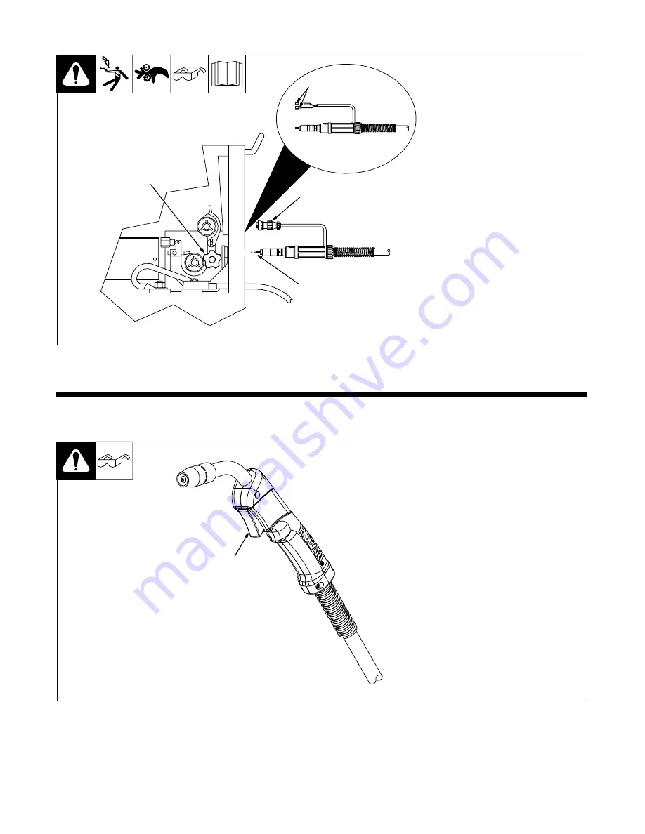
2-3. Installing Gun

243 861-A

1

Gun Securing Knob

2

Gun End

Loosen knob. Insert gun end until it

bottoms against drive assembly.

Tighten knob.
3

Gun Trigger Plug

Insert into receptacle, and tighten

threaded collar.
4

Friction Terminals

Some applications will require

cutting off trigger plug and installing

0.250 female friction terminals onto

end of leads.
See power source manual for

threading procedure.

1

3

2

4

SECTION 3 

 OPERATION

3-1. Operating The Gun

Ref. 243 838-A

1

Trigger Switch

When pressed, energized wire

feeds and shielding gas flows.

1

Содержание H100S4-10 Gun

Страница 1: ...H100S4 10 Gun Processes Description MIG GMAW Welding Semi Automatic Air Cooled MIG GTAW Welding Gun OM 245 987A 2009 12 Flux Cored FCAW Welding File MIG GMAW ...

Страница 2: ...ucts Please take time to read the Safety precautions They will help you protect yourself against potential hazards on the worksite We ve made installation and operation quick and easy With Hobart you can count on years of reliable service with proper maintenance And if for some reason the unit needs repair there s a Troubleshooting section that will help you figure out what the problem is The part...

Страница 3: ...LATION 3 2 1 Specifications 3 2 2 Duty Cycle And Overheating 3 2 3 Installing Gun 4 SECTION 3 OPERATION 4 3 1 Operating The Gun 4 SECTION 4 MAINTENANCE TROUBLESHOOTING 5 4 1 Removing Nozzle Contact Tip And Adapter Changing Liner And Cleaning Gun Casing 5 4 2 Replacing Switch And Or Head Tube 6 4 3 Routine Maintenance 7 4 4 Troubleshooting 7 SECTION 5 PARTS LIST 8 WARRANTY ...

Страница 4: ......

Страница 5: ...y especially children away ELECTRIC SHOCK can kill D Always wear dry insulating gloves D Insulate yourself from work and ground D Do not touch live electrode or electrical parts D Repair or replace worn damaged or cracked gun or cable insula tion D Turn off welding power source before changing contact tip or gun parts D Keep all covers and handle securely in place D Keep your head out of the fumes...

Страница 6: ...ned Until the final conclusions of the research are reached you may wish to minimize your exposure to electromagnetic fields when welding or cutting To reduce magnetic fields in the workplace use the following procedures 1 Keep cables close together by twisting or taping them or using a cable cover 2 Arrange cables to one side and away from the operator 3 Do not coil or drape cables around your bo...

Страница 7: ...E Exceeding duty cycle can damage unit and void warranty Overheating 0 15 A or V OR Reduce Duty Cycle Minutes sduty1 5 95 2 2 Duty Cycle And Overheating Duty Cycle is percentage of 10 minutes that gun can weld at rated load without overheating 0 10 Minutes Definition Continuous Welding 023 To 045 in 0 6 To 1 1 mm Hard Or Flux Cored Wires 100 Duty Cycle At 100 Amperes Using CO2 023 To 045 in 0 6 To...

Страница 8: ...sert into receptacle and tighten threaded collar 4 Friction Terminals Some applications will require cutting off trigger plug and installing 0 250 female friction terminals onto end of leads See power source manual for threading procedure 1 3 2 4 SECTION 3 OPERATION 3 1 Operating The Gun Ref 243 838 A 1 Trigger Switch When pressed energized wire feeds and shielding gas flows 1 ...

Страница 9: ...ze stamped on tip check and match wire size Tools Needed 8 mm 10 mm Lay gun cable out straight before installing new liner Remove nozzle contact tip and adapter Unscrew and remove liner Blow out gun casing Cut off wire and disconnect gun from feeder 5 8 in 16 mm Liner Stickout Install Liner Thread wire according to welding power source wire feeder manual Reassemble gun in reverse order from taking...

Страница 10: ...ndle halves and install switch housing Turn Off welding power source wire feeder and disconnect gun Remove switch housing Install new switch and connect leads polarity is not important Reassemble in reverse order If replacing head tube continue to end of figure 1 2 3 8 6 7 Remove screw on opposite side Secure head tube in vice Loosen jam nut Remove from vice and turn head tube out by hand 4 5 phil...

Страница 11: ... for kinks in gun cable Blow out liner and gun casing see Section 4 1 Weld porosity Remove weld spatter buildup in nozzle Check O rings on gun connector and replace if damaged Make sure inner head tube is tight in cable connector Check gun connector to be sure it is fully inserted into drive assembly Check shielding gas flow supply Wire feeding stops or does not feed properly during welding Straig...

Страница 12: ... 1 4 169 716 ADAPTER contact tip 1 5 246 373 TUBE head 1 6 243 865 NUT jam 1 7 242 832 HANDLE 1 8 225 410 SWITCH trigger 1 9 079 878 HOUSING PLUG PINS 1 10 246 380 HOUSING power pin 1 11 245 927 CONNECTOR feeder 1 12 197 123 O RING 312 ID X 062 70 duro buna n 2 13 194 010 LINER monocoil 023 025 wire x 15ft consisting of 1 13 194 011 LINER monocoil 030 035 wire x 15ft consisting of 1 13 194 012 LIN...

Страница 13: ... 9 Notes FILLET GROOVE WELD JOINT TYPES BUTT BUTT BUTT BUTT T JOINT T JOINT T JOINT T JOINT FLAT VERTICAL HORIZONTAL OVERHEAD WELD POSITION Ref AWS ANSI D1 1 1G 1F 2G 2F 3G 3F 4G 4F Ref 804 248 A ...

Страница 14: ...Notes ...

Страница 15: ... to 1 Consumable components such as contact tips cutting nozzles slip rings drive rolls gas diffusers plasma torch tips and electrodes weld cables and tongs and tips or parts that fail due to normal wear Exception brushes slip rings and relays are covered on Hobart Engine Driven models 2 Items furnished by Hobart Miller but manufactured by others such as engines or trade accessories These items ar...

Страница 16: ...utor retail or service location Call 1 877 Hobart1 or visit our website at www HobartWelders com Contact your Distributor for Welding Supplies and Consumables Options and Accessories Personal Safety Equipment Service and Repair Replacement Parts Training Schools Videos Books Technical Manuals Servicing Information and Parts Circuit Diagrams Welding Process Handbooks Contact the Delivering Carrier ...

Отзывы: