Installation
9 (24)
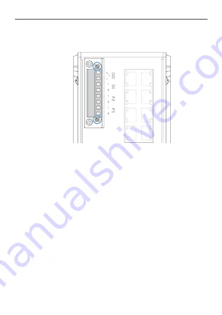
4.4
Installing Terminal Block
Procedure
1.
Attach the terminal block to the contact on the switch.
2.
Fasten the terminal block with the 2 screws included.
Anybus
®
Managed Industrial L3 Switch Startup Guide
SP2556 1.1 en-US
Страница 1: ...Anybus Managed Industrial L3 Switch STARTUP GUIDE SP2556 1 1 en US ENGLISH...
Страница 2: ...of possible applications of the product and because of the many variables and requirements associated with any particular implementation HMS Industrial Networks cannot assume responsibility or liabil...
Страница 3: ...t and Resources 5 4 Installation 6 4 1 DIN Rail Mounting 6 4 2 Connecting Ground Screw 7 4 3 Terminal Block Connector 8 4 4 Installing Terminal Block 9 4 5 Connecting Digital Output Wires 10 4 6 Conne...
Страница 4: ...ndustrial L3 Switch Startup Guide SP2556 1 1 en US 6 Verify Operation 19 6 1 System LED Indicators 19 6 2 Ethernet LED Indicators 20 6 3 SFP Port LED Indicators 21 7 Technical Data 22 7 1 Technical Sp...
Страница 5: ...cument WARNING Instruction that must be followed to avoid a risk of death or serious injury Caution Instruction that must be followed to avoid a risk of personal injury Instruction that must be follow...
Страница 6: ...t specified by the manufacturer the protection provided by the equipment may be impaired 2 2 General Safety Caution Ensure that the power supply is turned off before connecting it to the switch Connec...
Страница 7: ...heet 1 3 2 Support and Resources For additional documentation and software downloads FAQs troubleshooting guides and technical support please visit www anybus com support Have the product article numb...
Страница 8: ...DIN rail in accordance with the EN 50022 standard Procedure Mount the switch on a DIN rail 1 Insert the upper end of the DIN rail clip into the DIN rail 2 Push the bottom of the DIN rail clip into the...
Страница 9: ...avoid system damage the switch should be connected to ground Procedure 1 Establish a direct connection between the ground screw and the grounding surface prior to connecting devices Anybus Managed Ind...
Страница 10: ...onnector Contact Number Description 1 DO Digital Output 2 3 DI Digital Input 4 DI Digital Input 5 P2 Power Input 2 6 P2 Power Input 2 7 P1 Power Input 1 8 P1 Power Input 1 Anybus Managed Industrial L3...
Страница 11: ...4 4 Installing Terminal Block Procedure 1 Attach the terminal block to the contact on the switch 2 Fasten the terminal block with the 2 screws included Anybus Managed Industrial L3 Switch Startup Guid...
Страница 12: ...triggered the two wires attached to the DO fault contacts form a close circuit The fault circuit remains opened until a user configured event occur Procedure Connect the Digital Output DO 1 Insert th...
Страница 13: ...gital Input Wires Procedure Connect the Digital Input DI 1 Insert the wires into the 2 pin DI and DI contact on the 8 pin terminal block 2 Tighten the wire clamp screws Anybus Managed Industrial L3 Sw...
Страница 14: ...ent 24 VDC Procedure 1 Connecting to main power supply P1 Insert the positive and negative wires into the P1 and P1 contact on the 8 pin terminal block 2 Connecting to redundant power supply P2 Insert...
Страница 15: ...Installation 13 24 4 8 Connecting to Ethernet Network Optional Connect the switch to an Ethernet network Anybus Managed Industrial L3 Switch Startup Guide SP2556 1 1 en US...
Страница 16: ...Installation 14 24 4 9 Connecting to Fiber Network Optional Connect the switch to a network via the SFP port Anybus Managed Industrial L3 Switch Startup Guide SP2556 1 1 en US...
Страница 17: ...er Connect the switch to power To link your computer with the switch make sure that the IP address of the computer is located in the same subnet as the switch default IP address Procedure Access the w...
Страница 18: ...ough console management 2 Go to Start Program Accessories Communication Hyper Terminal 3 Give the new console connection a name 4 Choose COM name 5 Select correct serial settings Baud Rate 115200 Pari...
Страница 19: ...B Port Use the USB port in order to save or restore the configuration and upload the firmware upgrade file For further configurations refer to the User Manual Anybus Managed Industrial L3 Switch Start...
Страница 20: ...is powered on 2 Use a pointed object such as a ballpoint pen to press and hold the reset button for 10 seconds Result Once the reset button is released the switch reboot automatically When the switch...
Страница 21: ...SYS System status Green On Ready Green blinking Firmware updating Off Not Ready Ring Ring status Green On Not Owner Normal Green blinking Owner Normal Amber On Abnormal Amber blinking Ring Port Failur...
Страница 22: ...10 100 100 Base T LED Status Description A Status Green On Link established Green Blinking Packets transmitting receiving Green Off Link is inactive B Link Activity Amber On Link Speed 1 Gbit s Amber...
Страница 23: ...ort 100 1000 Base SFP DDM LED Status Description SFP Port Green On Link established Green blinking Packets transmitting receiving Green Off Link is inactive Amber On Link Speed 1 Gbit s Amber Off Link...
Страница 24: ...using material Steel aluminium IP protection class IP31 Dimensions 85 5 x 150 x 126 5 W x H x D without DIN Rail Clip Mounting DIN rail Configuration CGI WebGUI Command Line Interface CLI SNMP Securit...
Страница 25: ...4 IPv6 SNMP v1 v2c v3 RMON LLDP DHCP server client Option 82 SysLog Standards IEC60950 1 Compliance EN61000 6 2 EN61000 6 4 CISPR 22 FCC part 15B Class A EN61000 4 2 ESD EN61000 4 3 RS EN61000 4 4 EFT...
Страница 26: ...last page 2019 HMS Industrial Networks Box 4126 300 04 Halmstad Sweden info hms se SP2556 1 1 en US 2019 10 30 15741...